mutantC_v5 All the info you need to make one
mutantC_v5 features
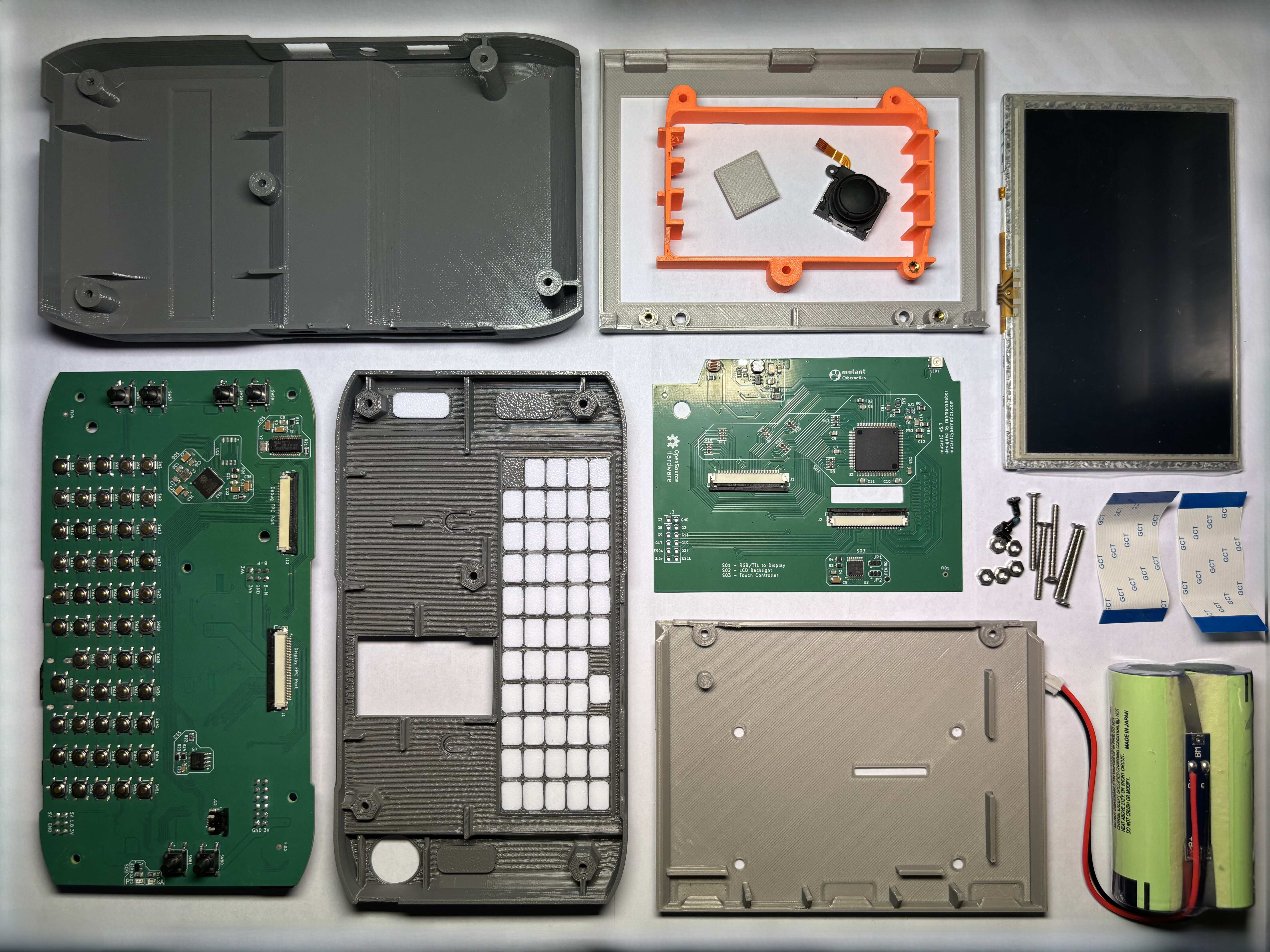
mutantC_v5 is the successor to mutantC_V4 with more features.
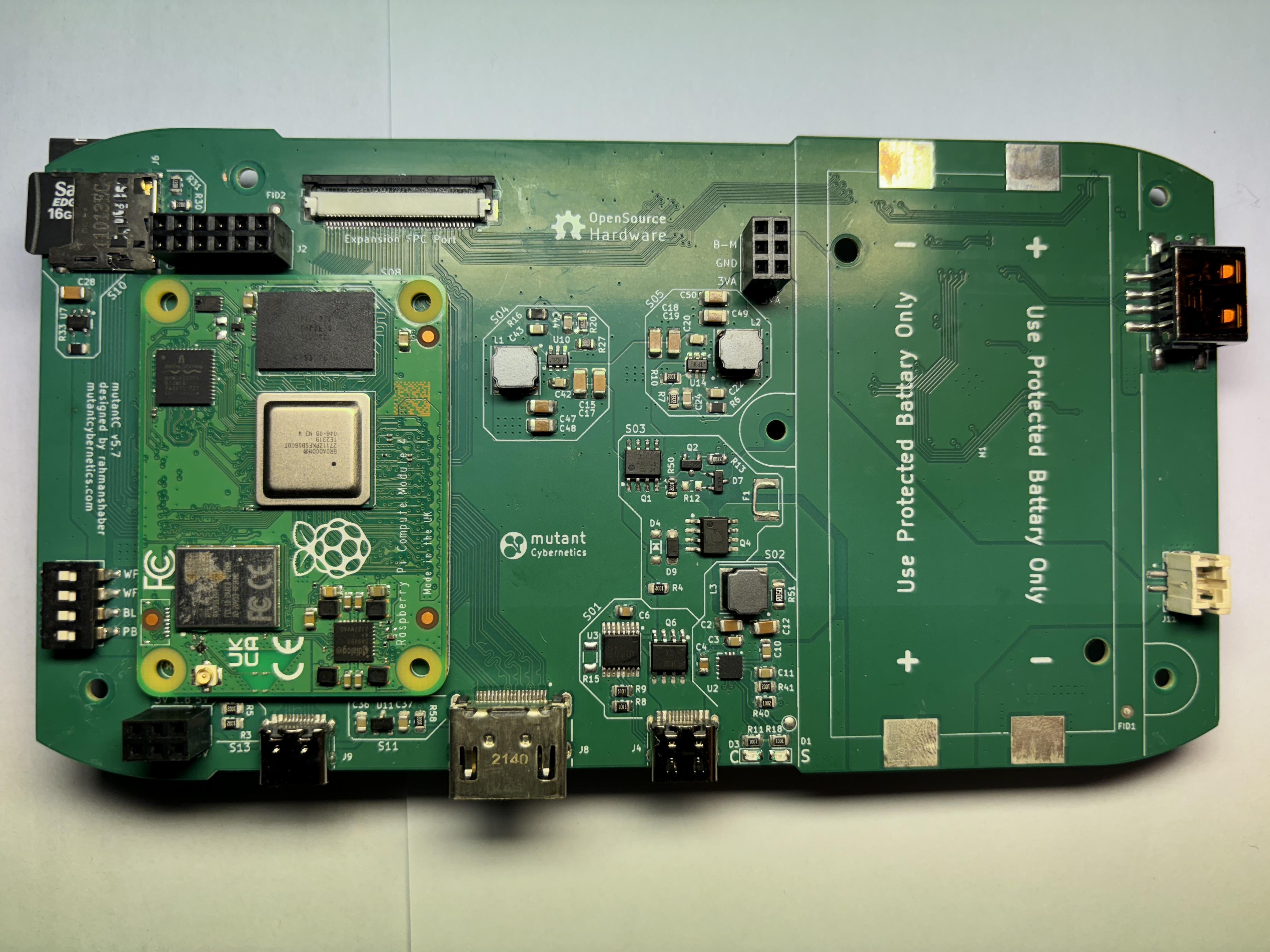
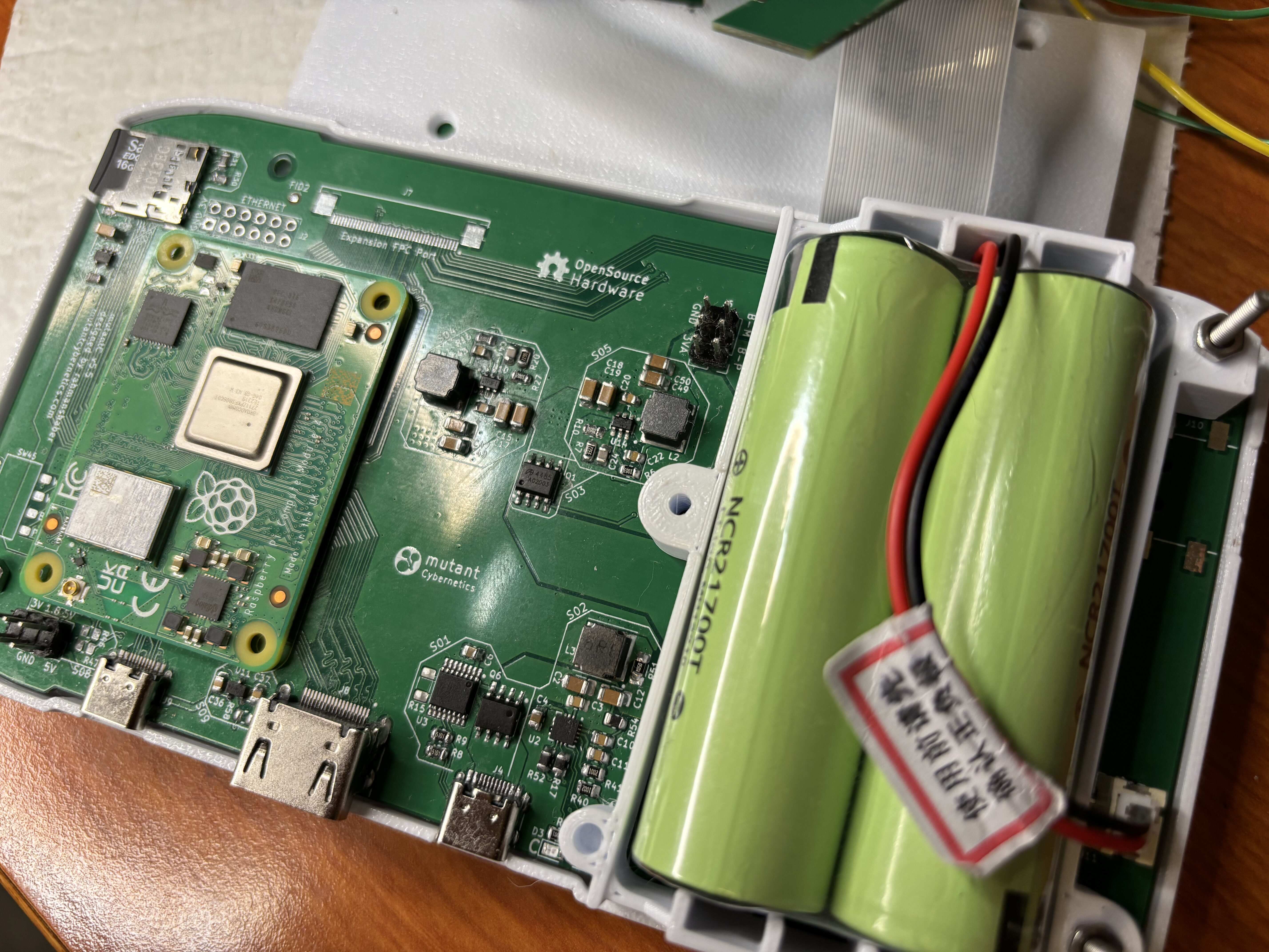
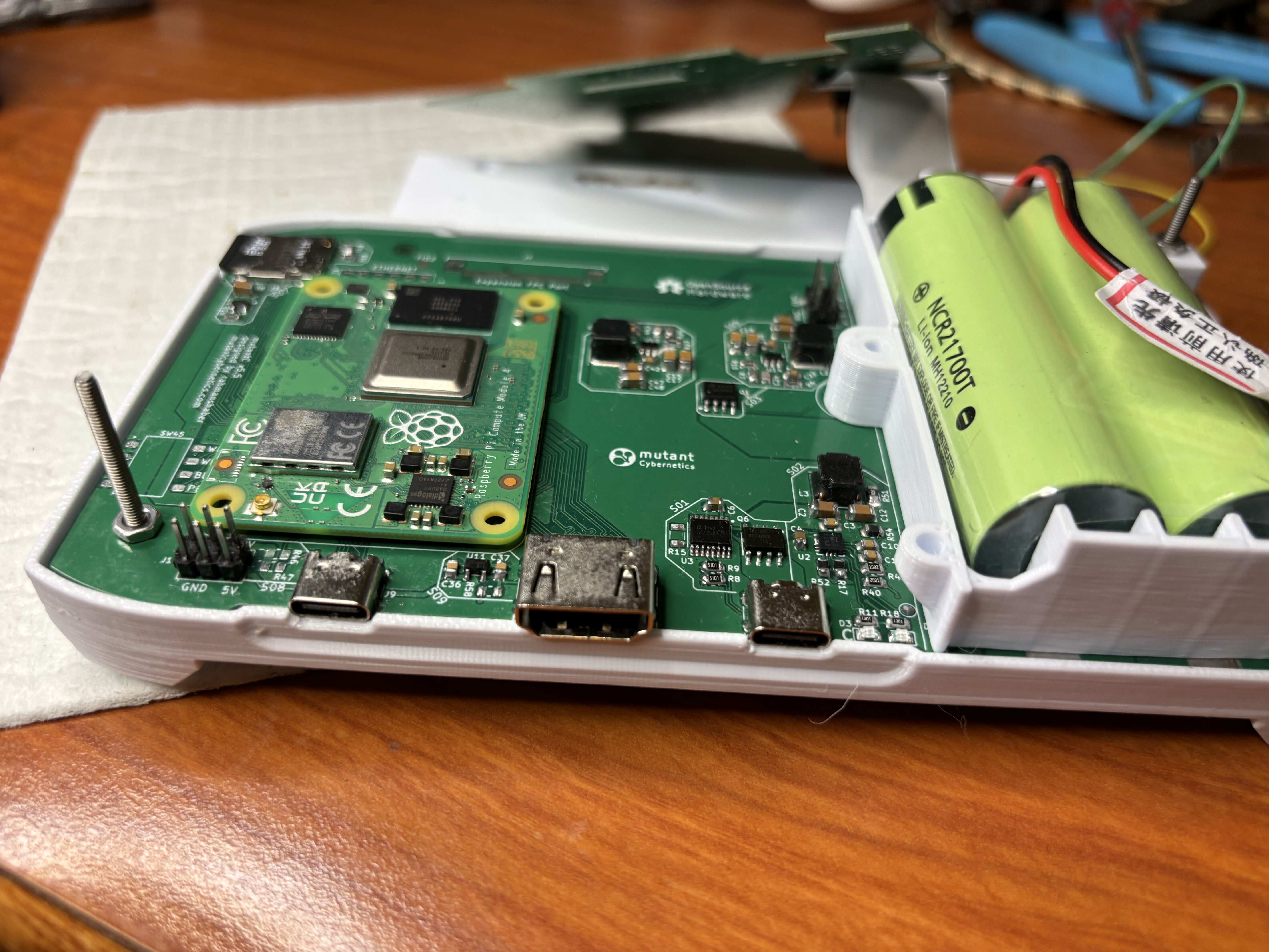
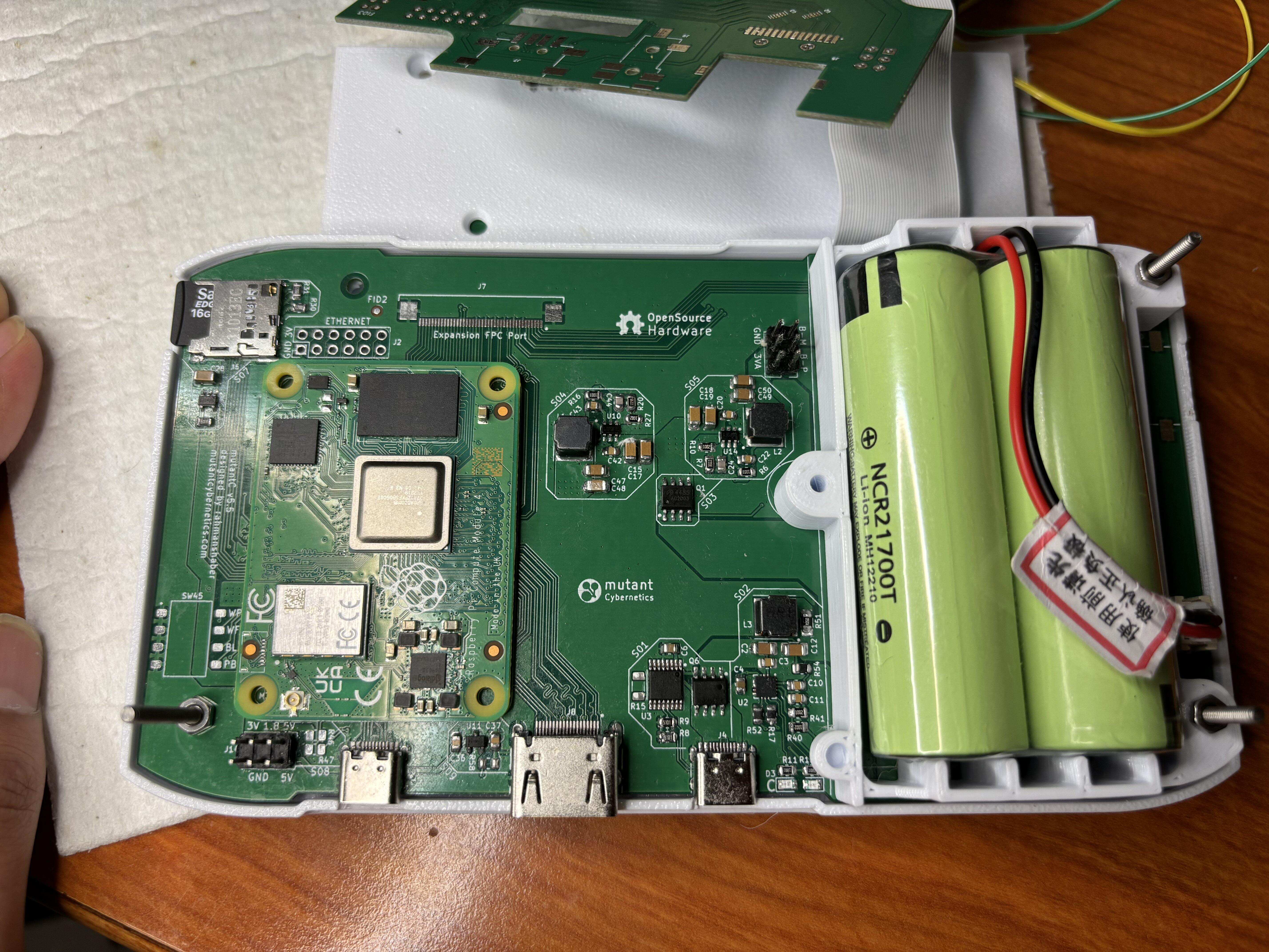
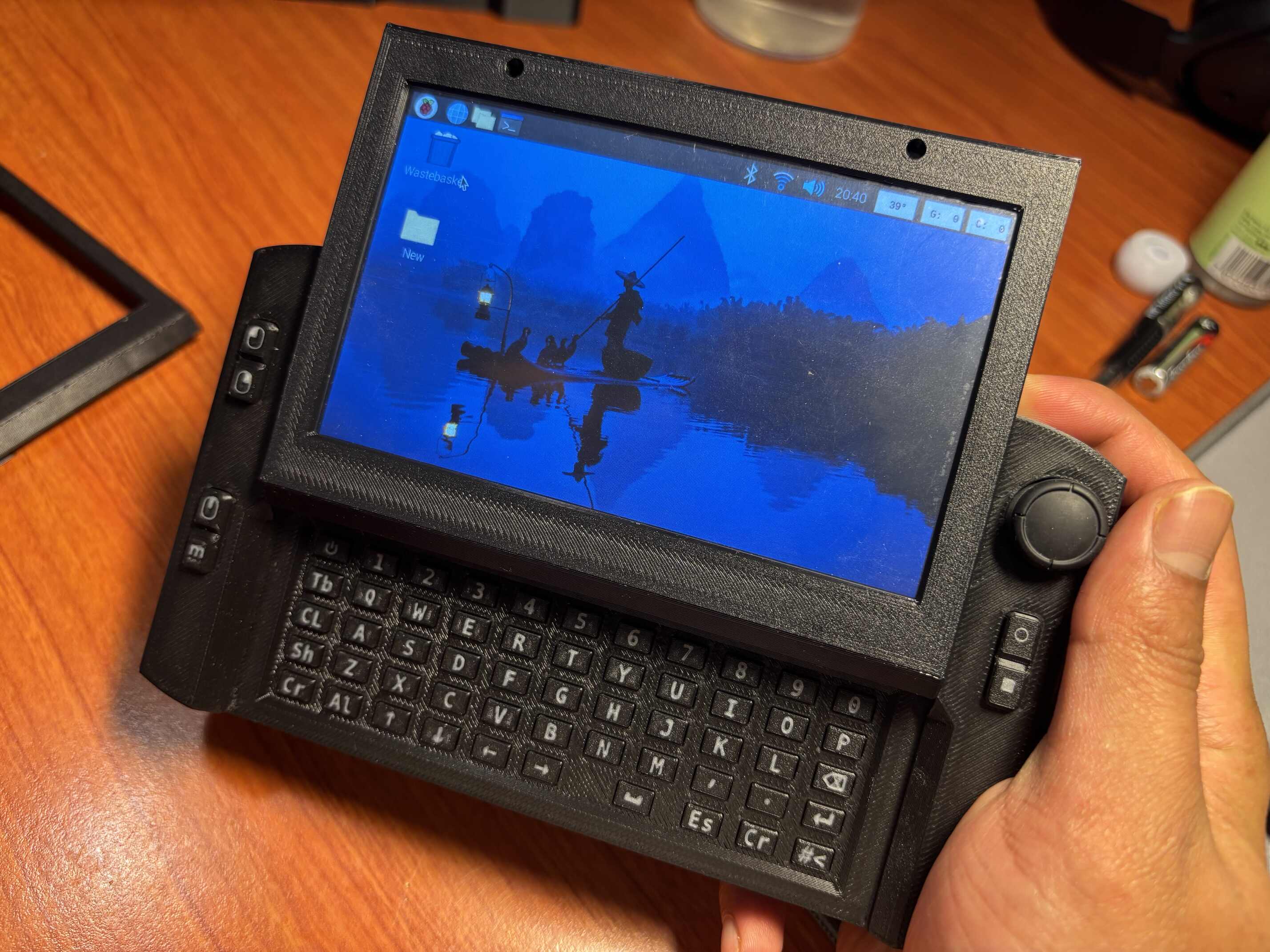
- Uses Raspberry Pi CM4 form factor as the main SBC.
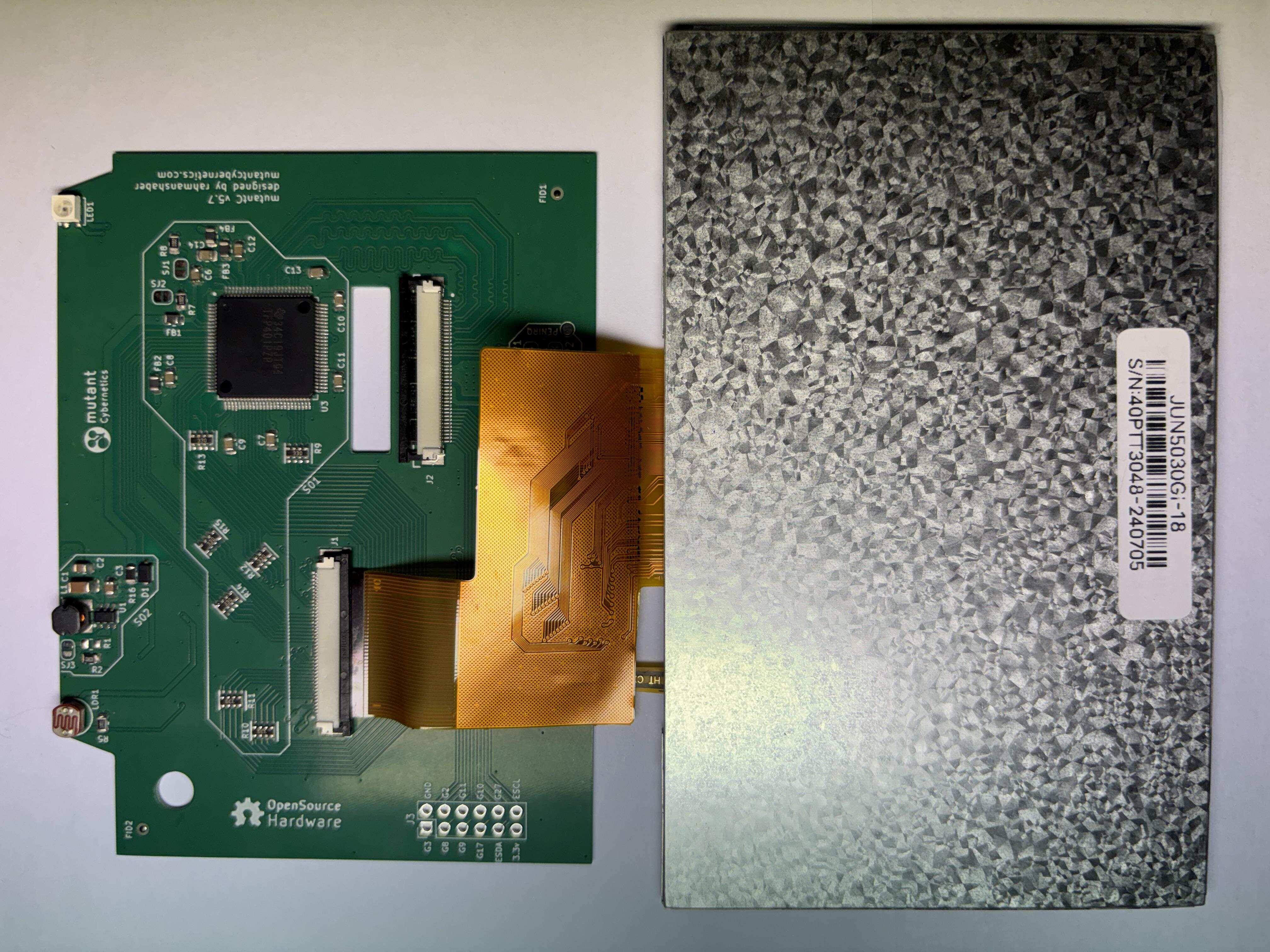
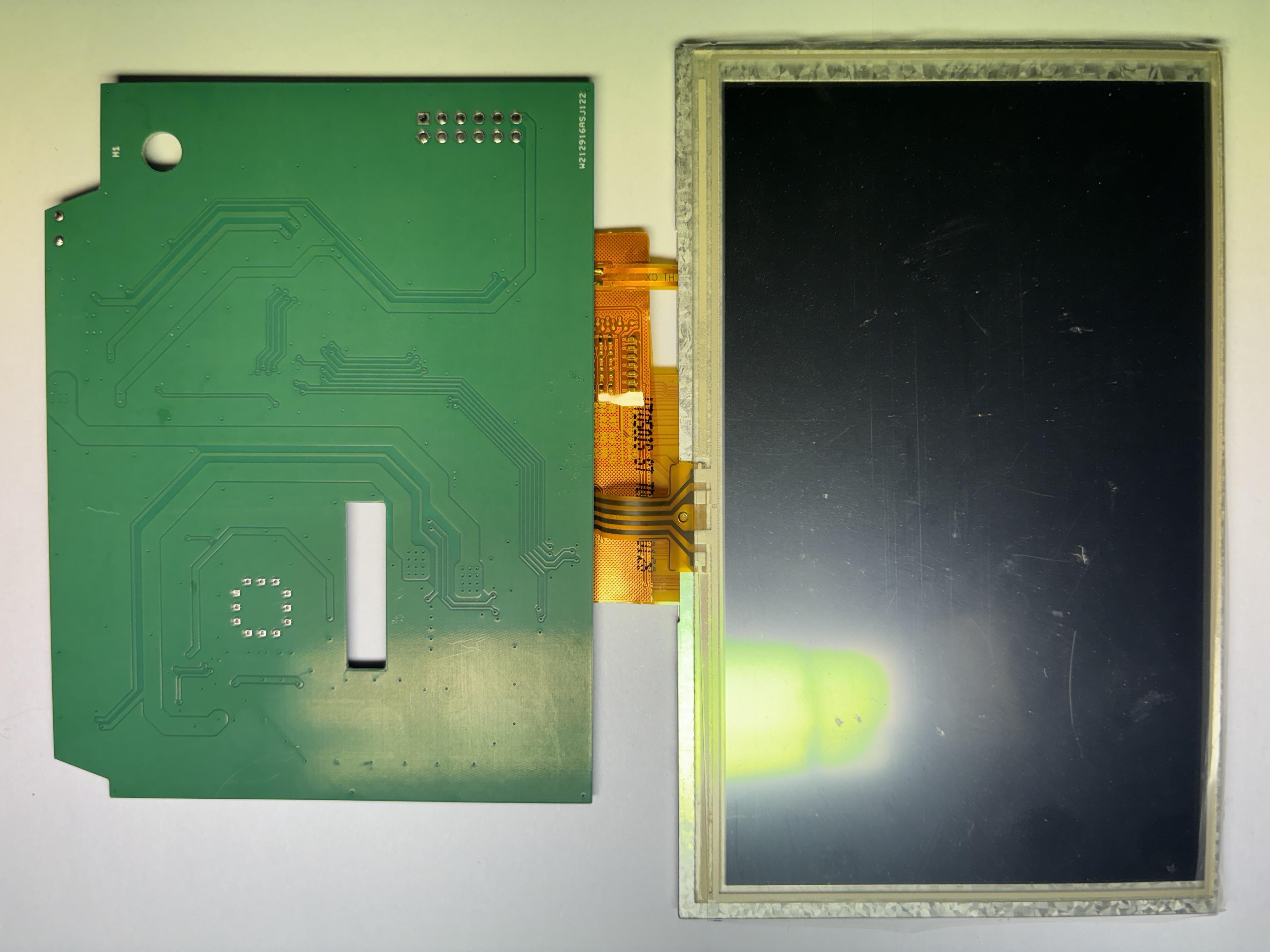
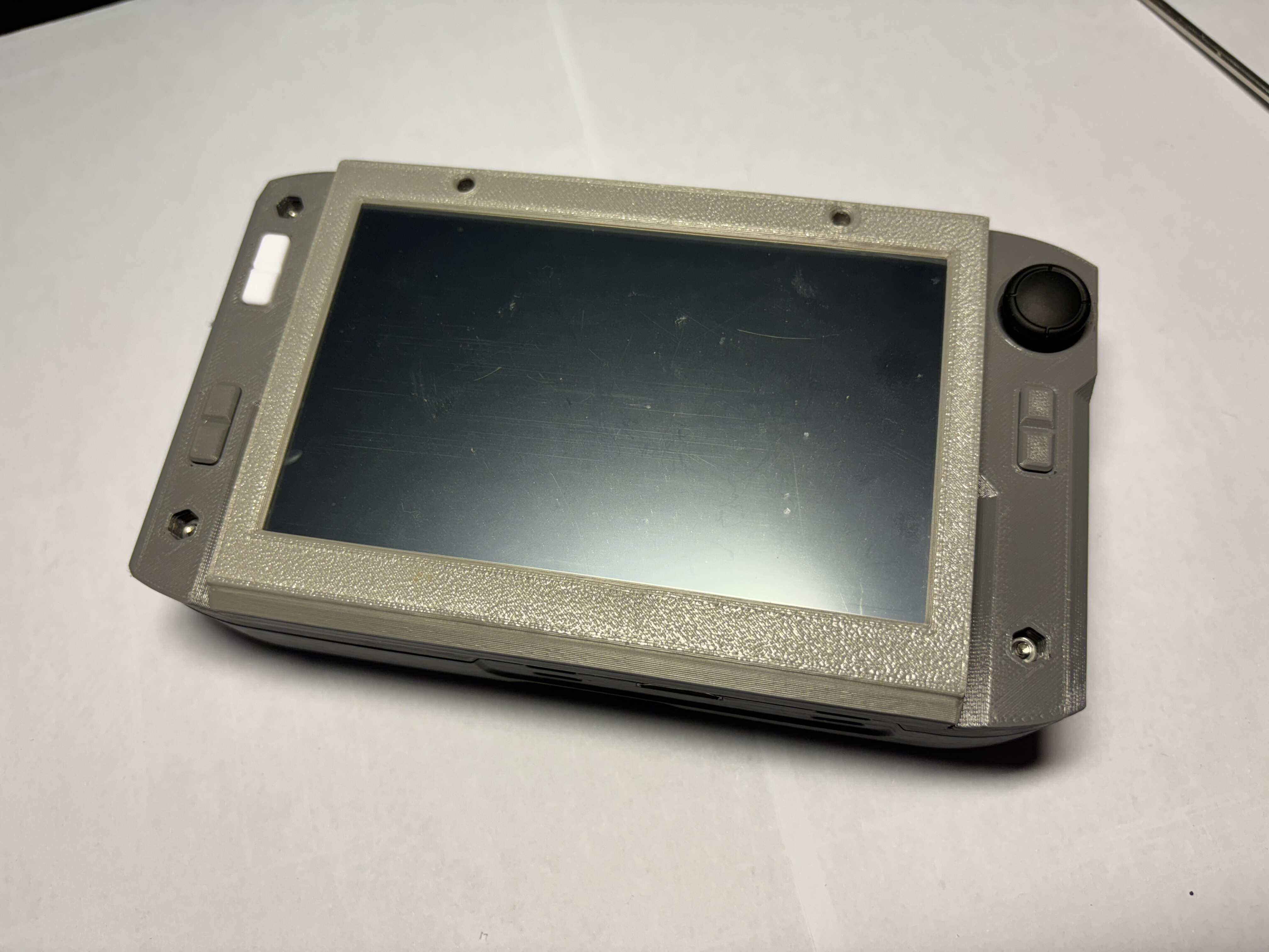
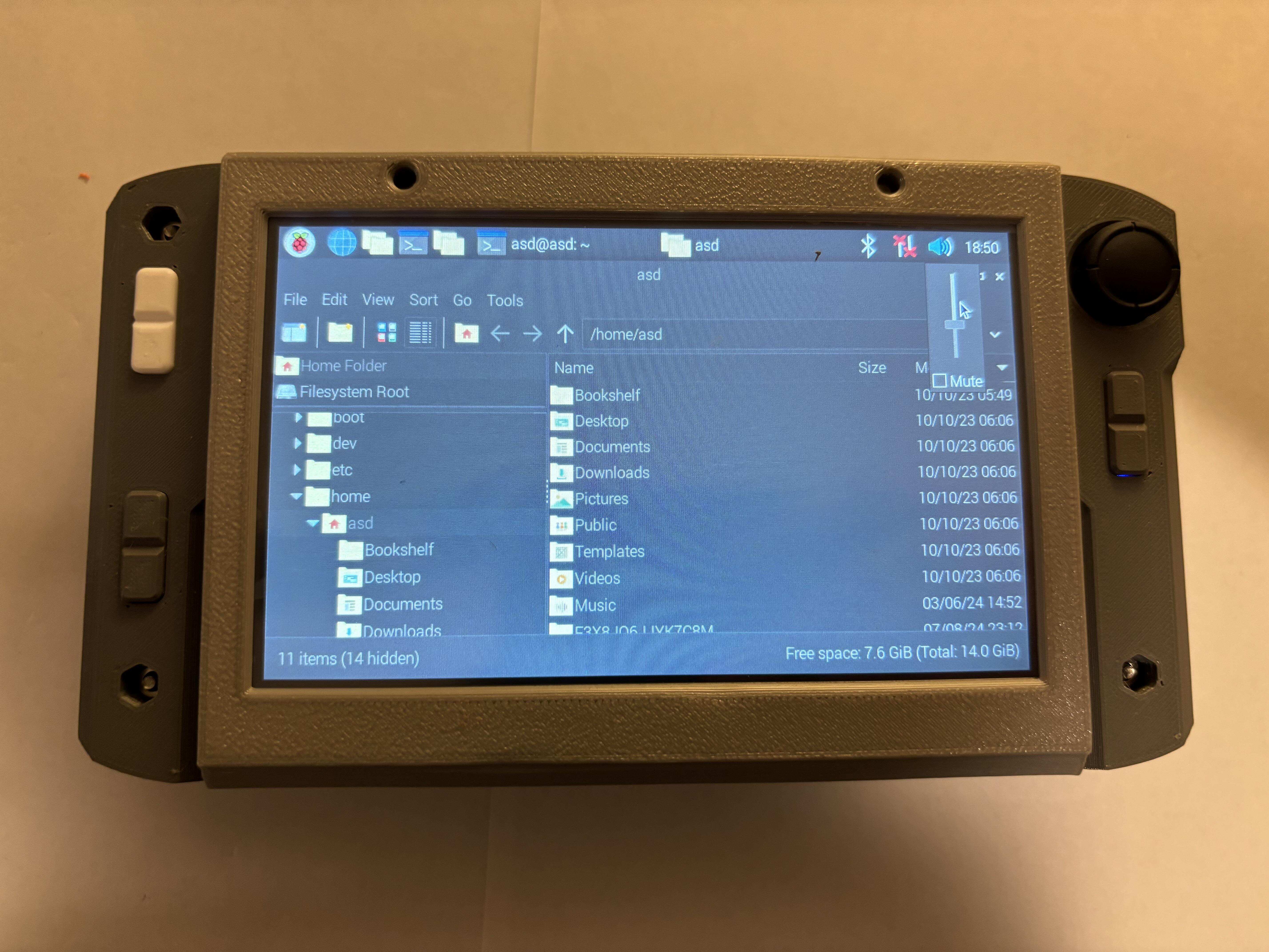
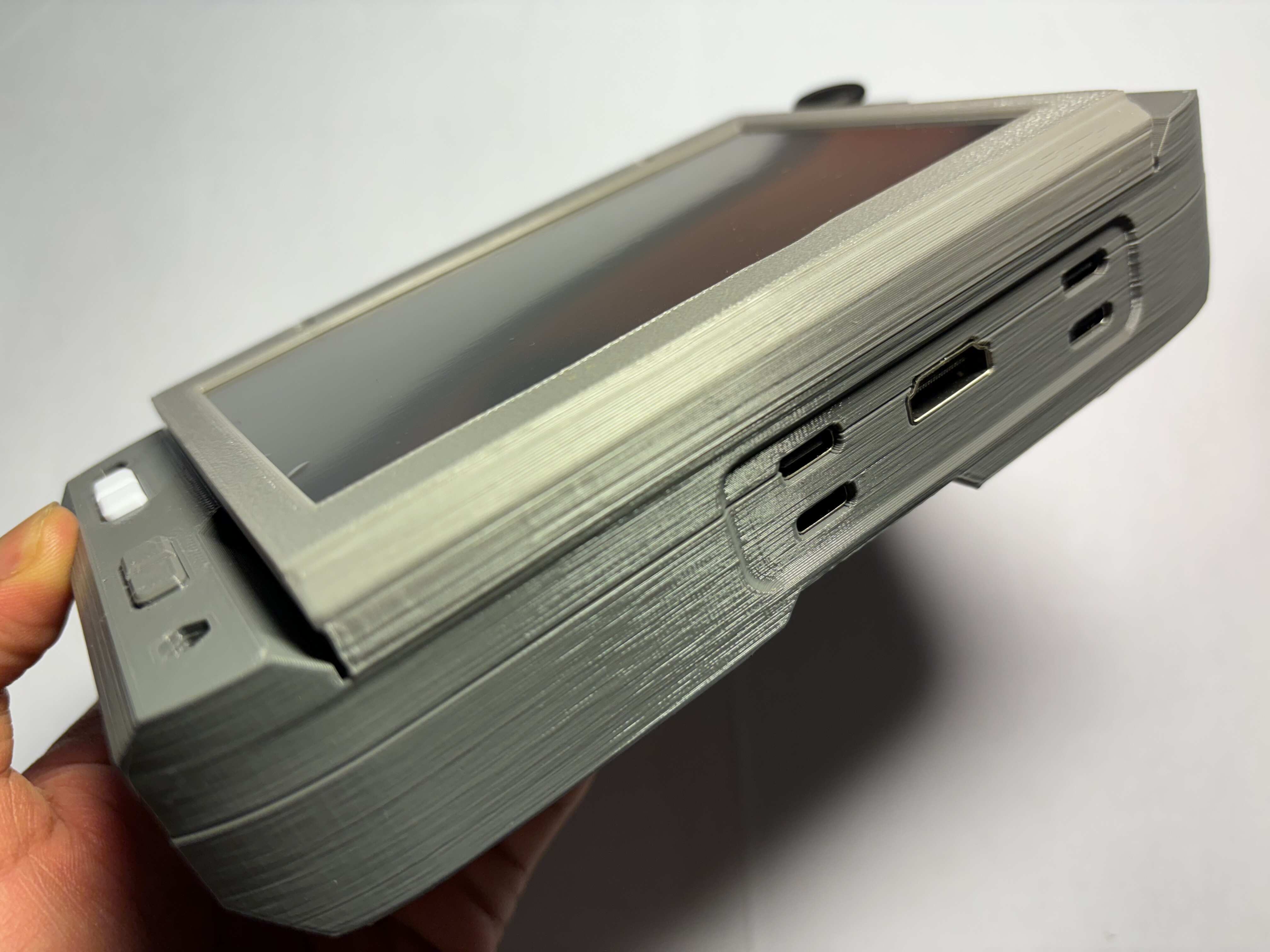
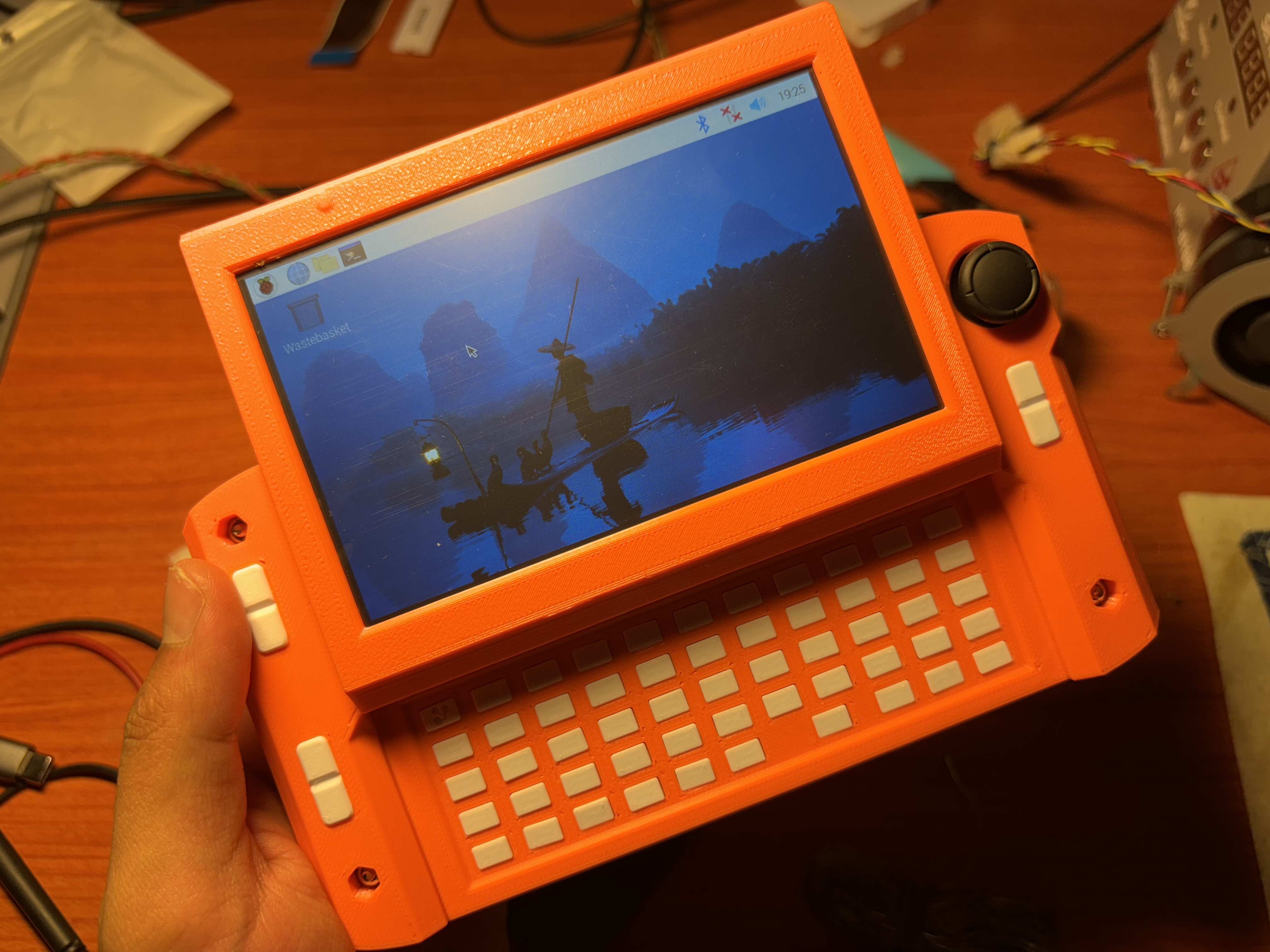
- 5-inch or 4.3-inch LCD plus an external display output port.
- 1, 2, 4, or 8 GB RAM; Wi-Fi; storage via eMMC or SD card (depending on SBC).
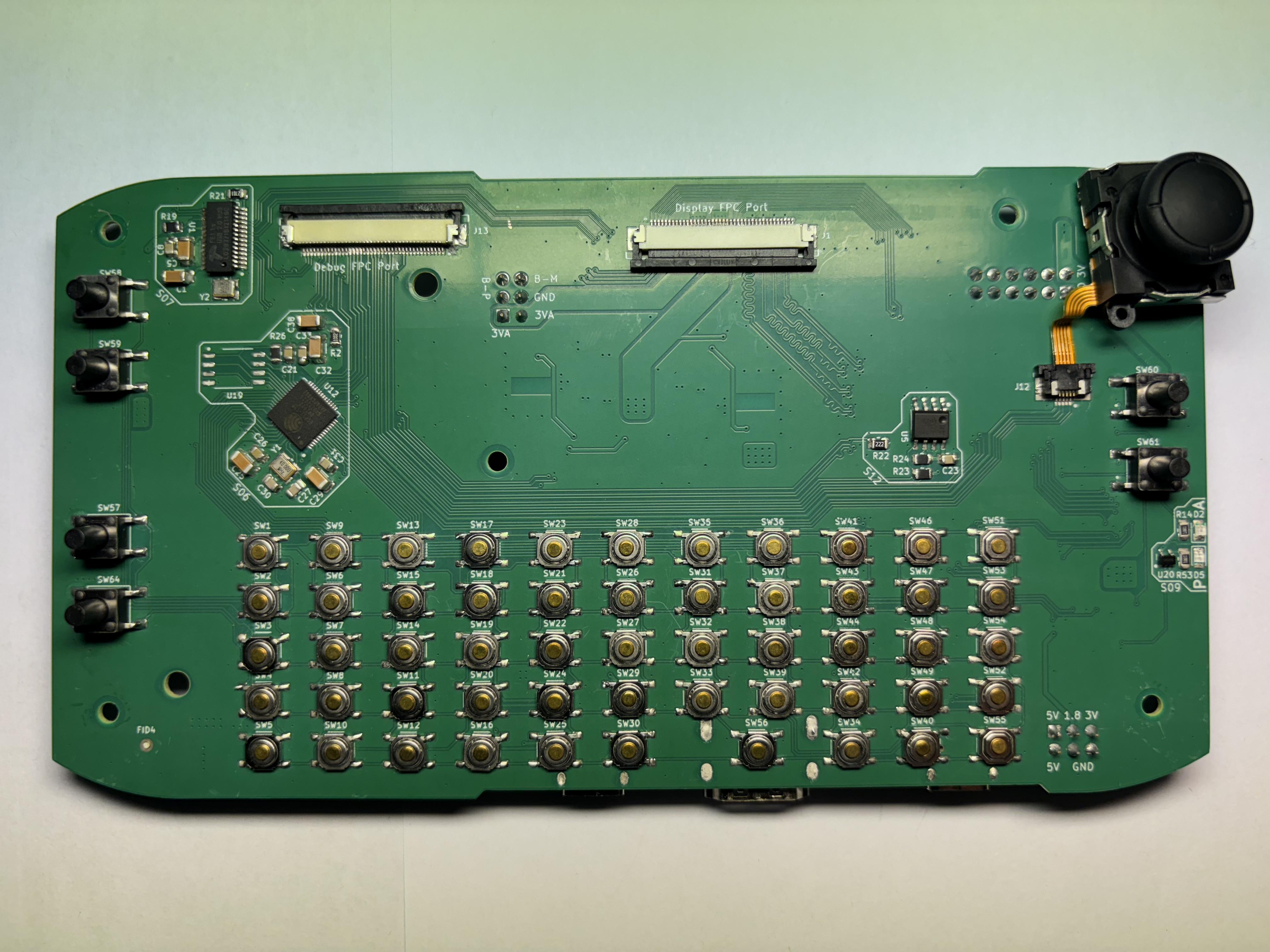
- ESP32-S2 handles secondary functions including keyboard and mouse control.
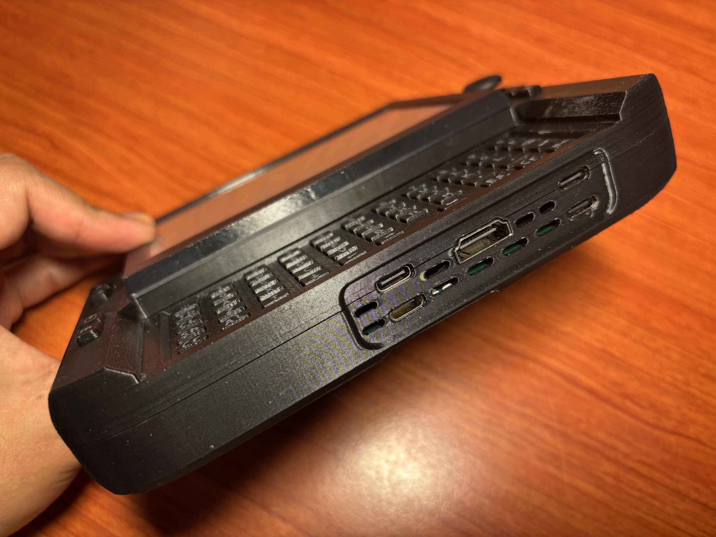
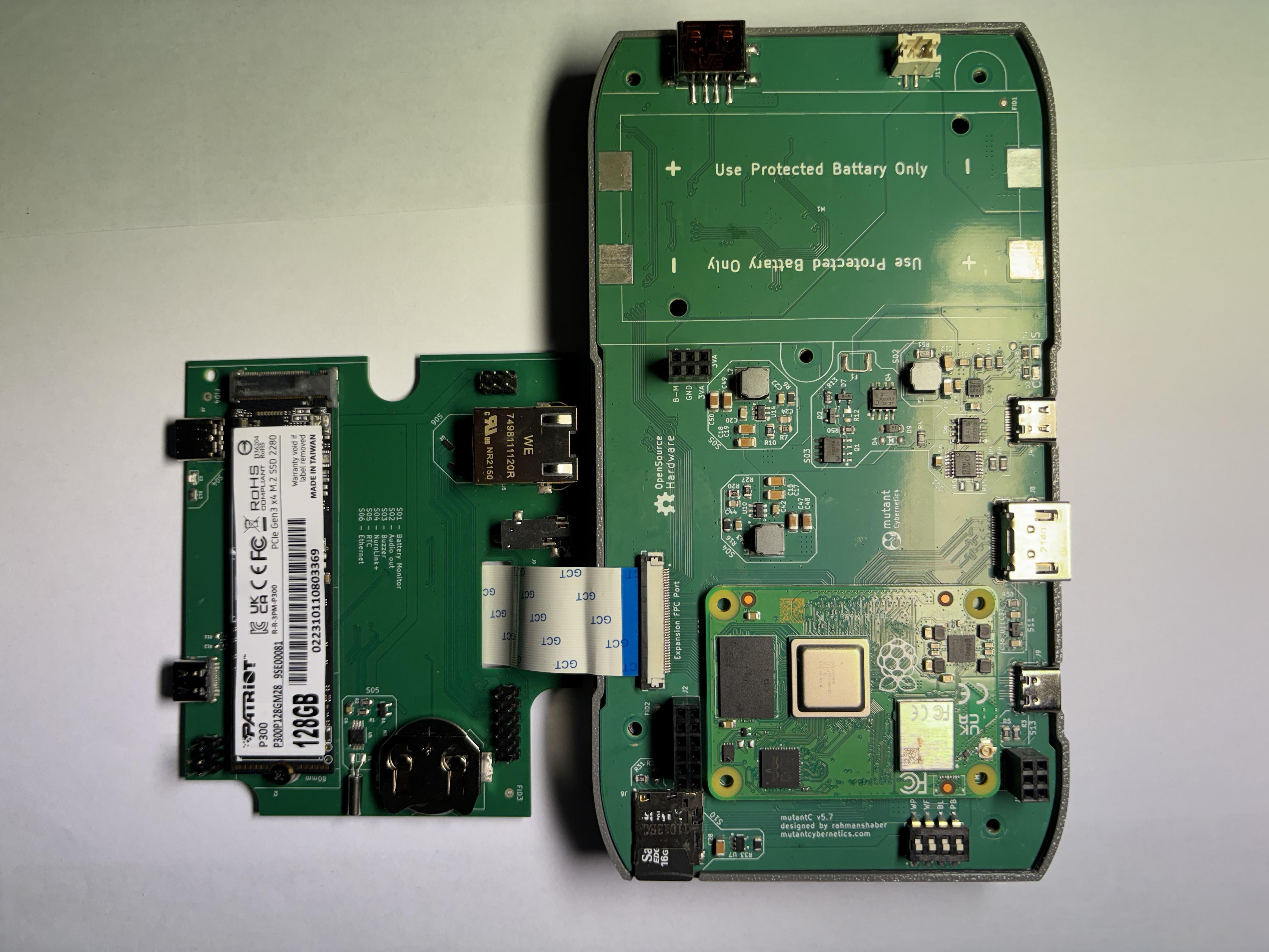
- Expansion provides a PCIe Gen2 x1 lane for add-on cards (e.g. SSDs, OCuLink support).
- Expansion exposes two USB 2.0 ports and 17 GPIO pins including SPI, I2C, and PWM.
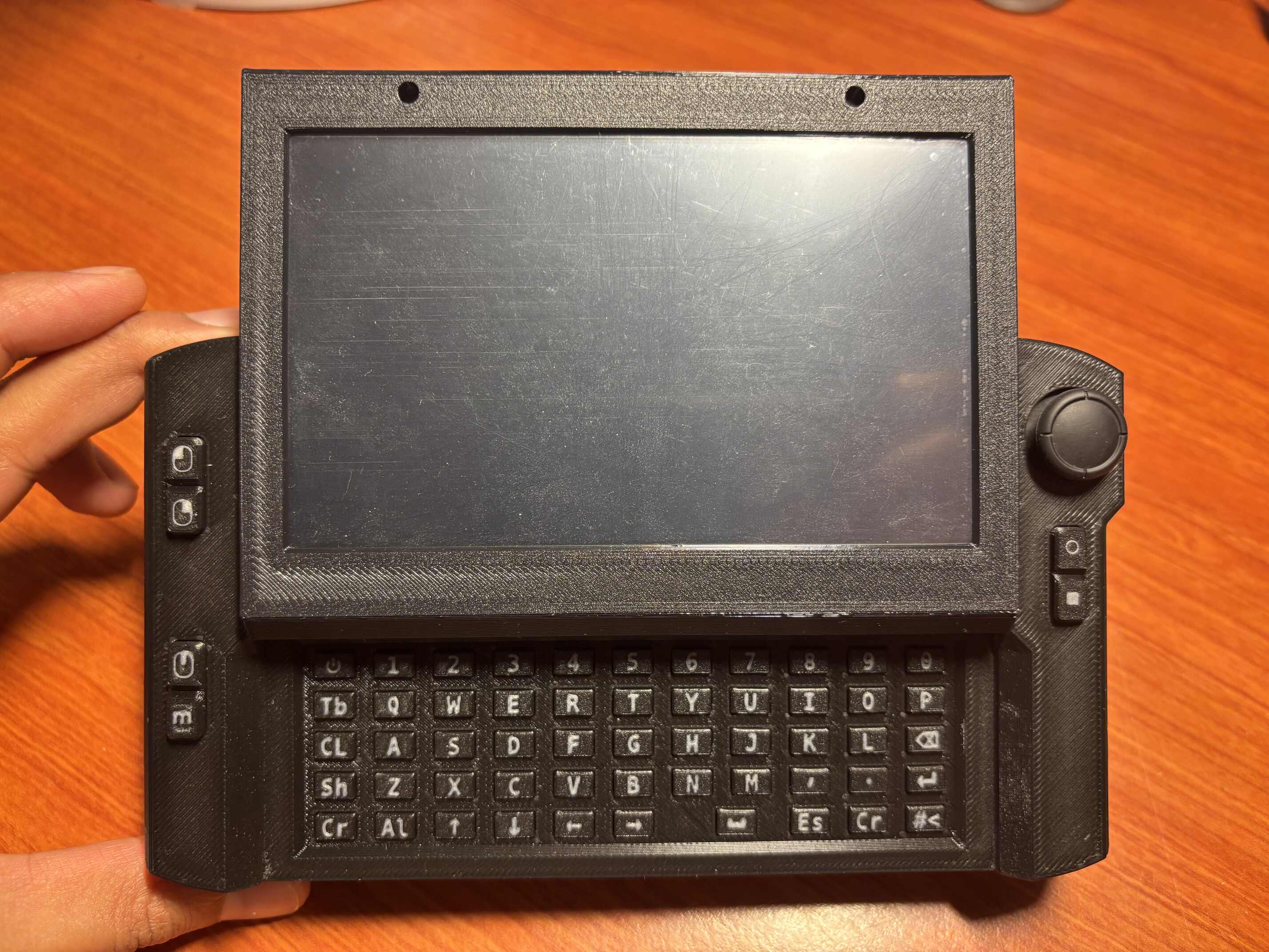
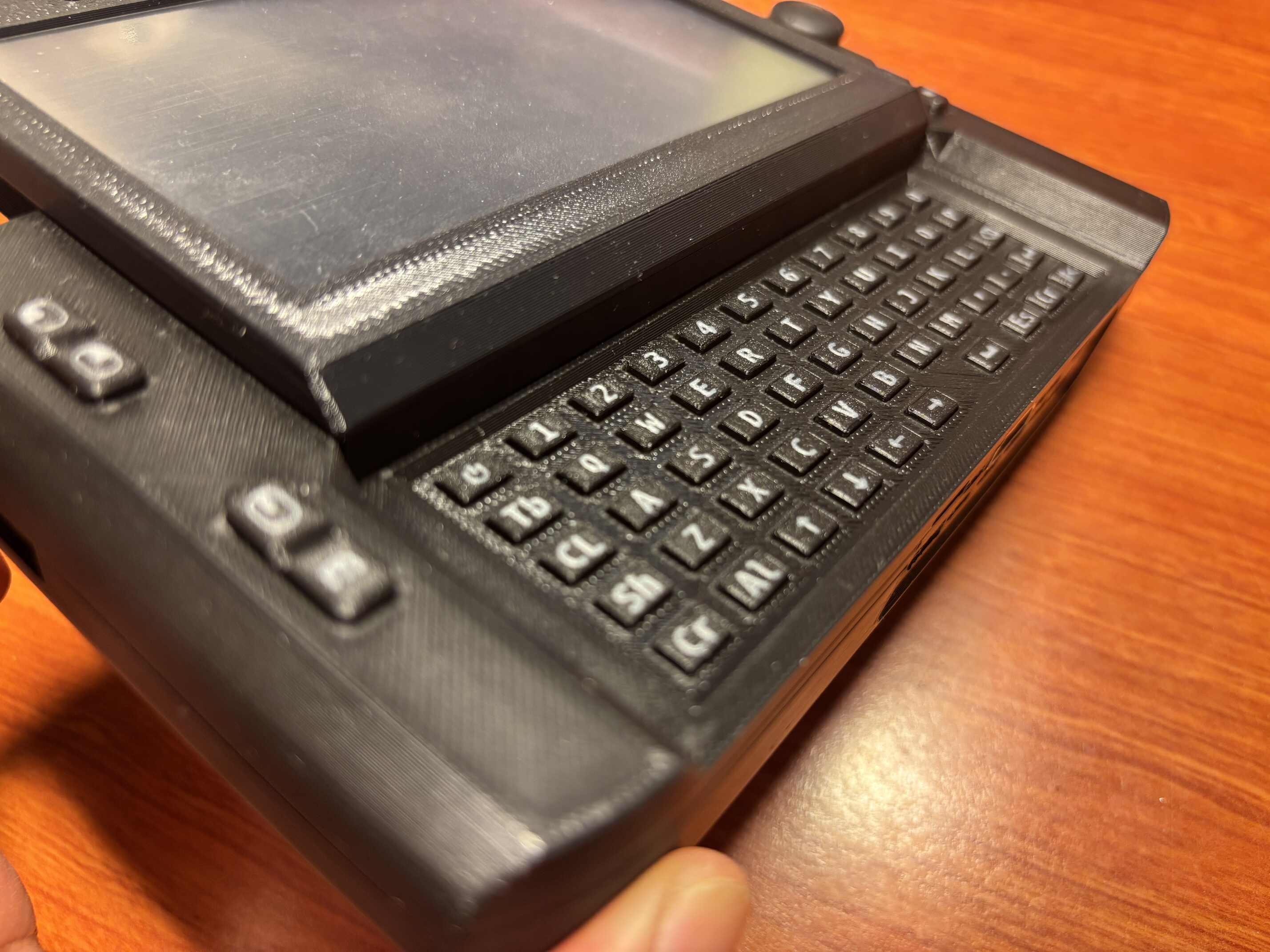
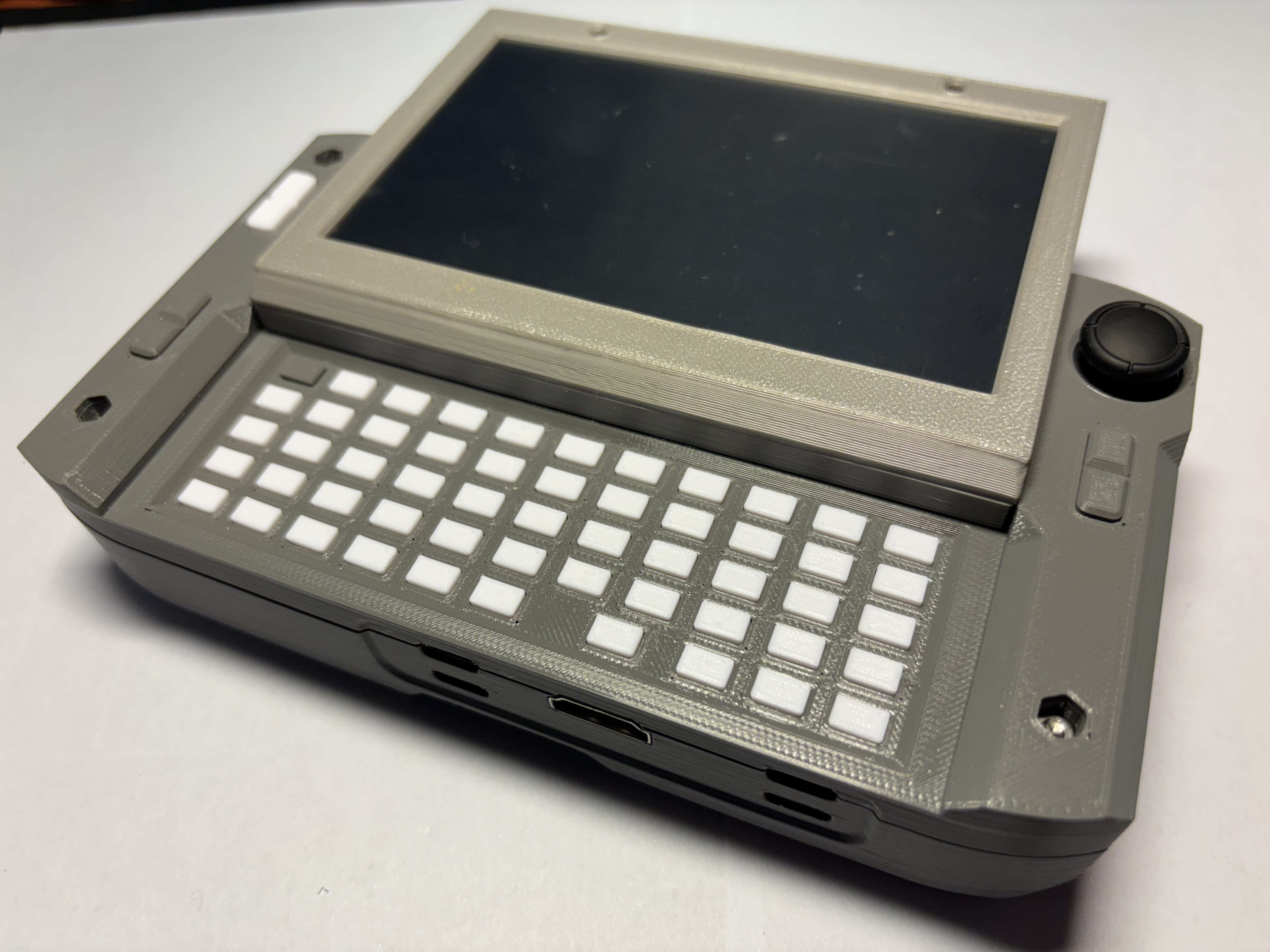
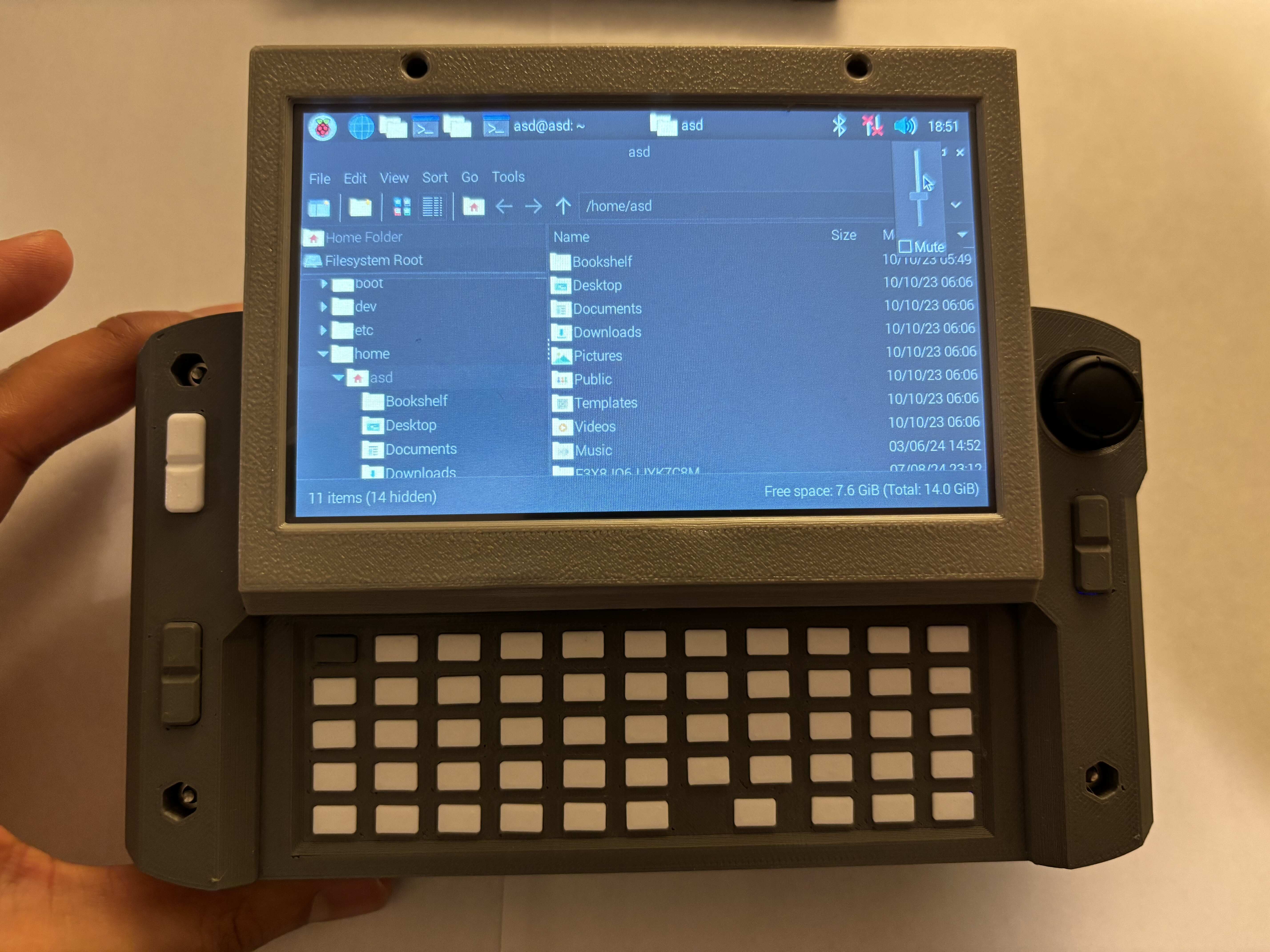
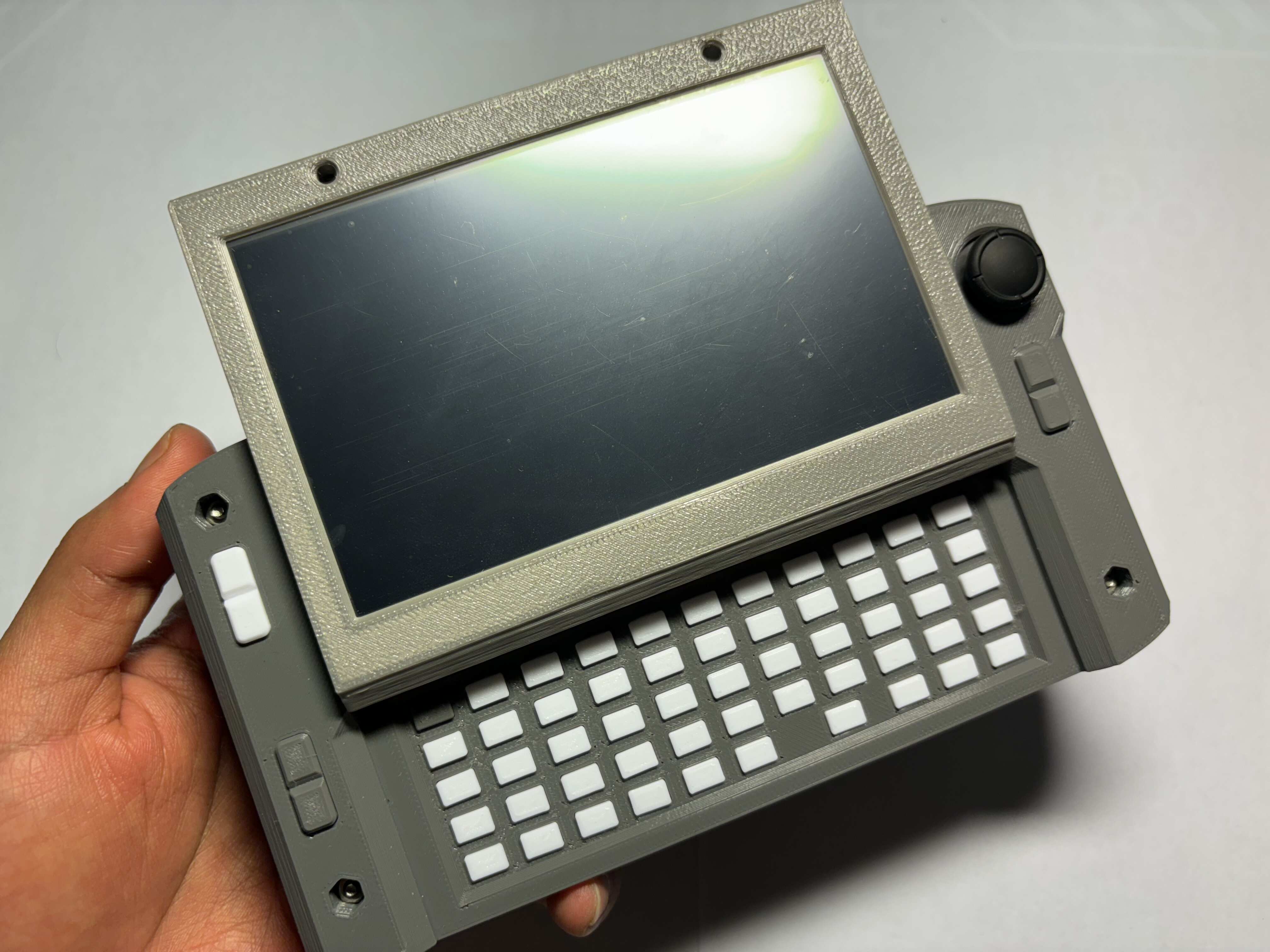
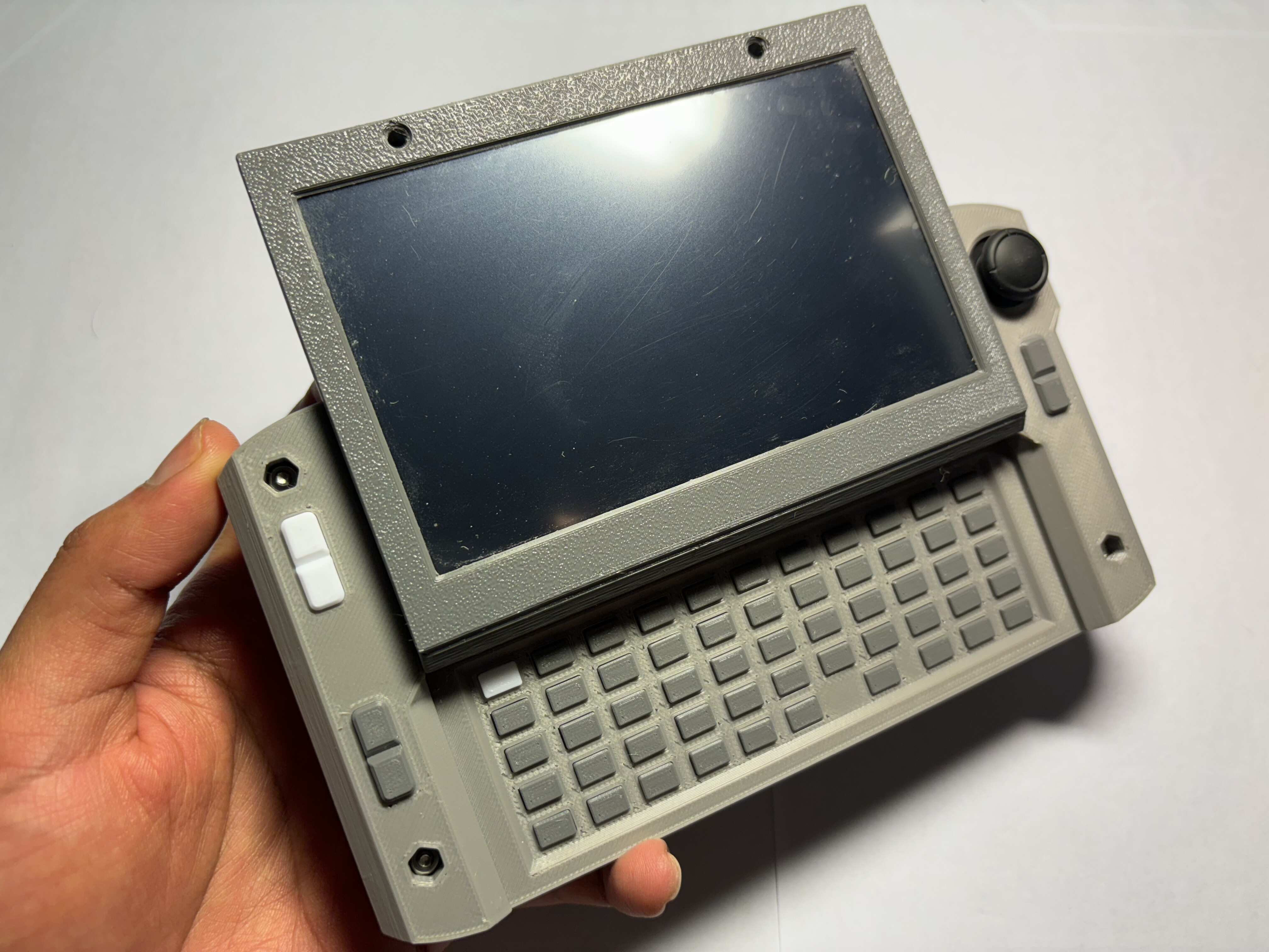
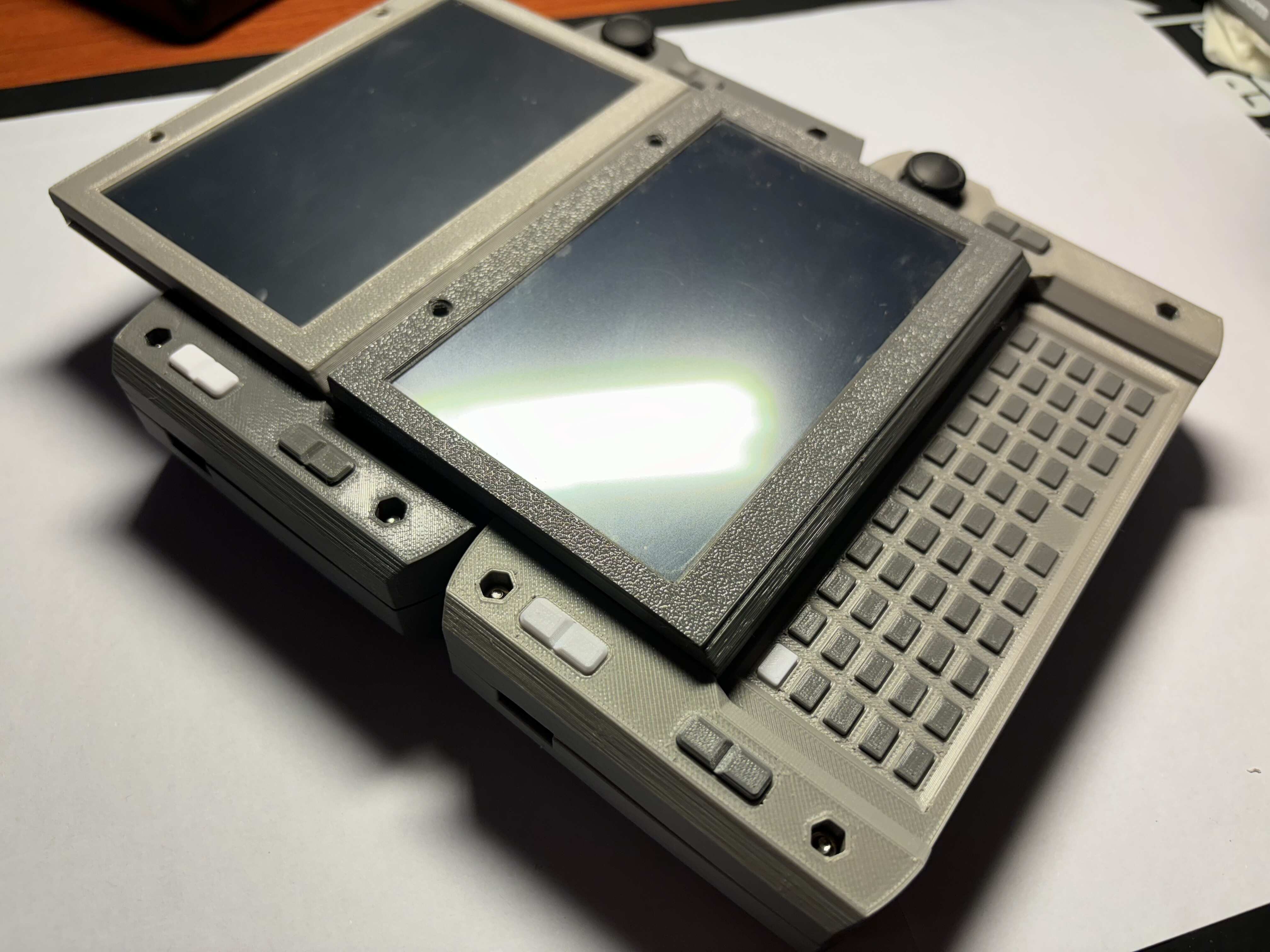
- 61-key customizable keyboard and six shoulder buttons for navigation.
- 3D Hall-effect joystick for precise mouse control.
- NeoPixel LED connected to the main SBC for customizable notifications.
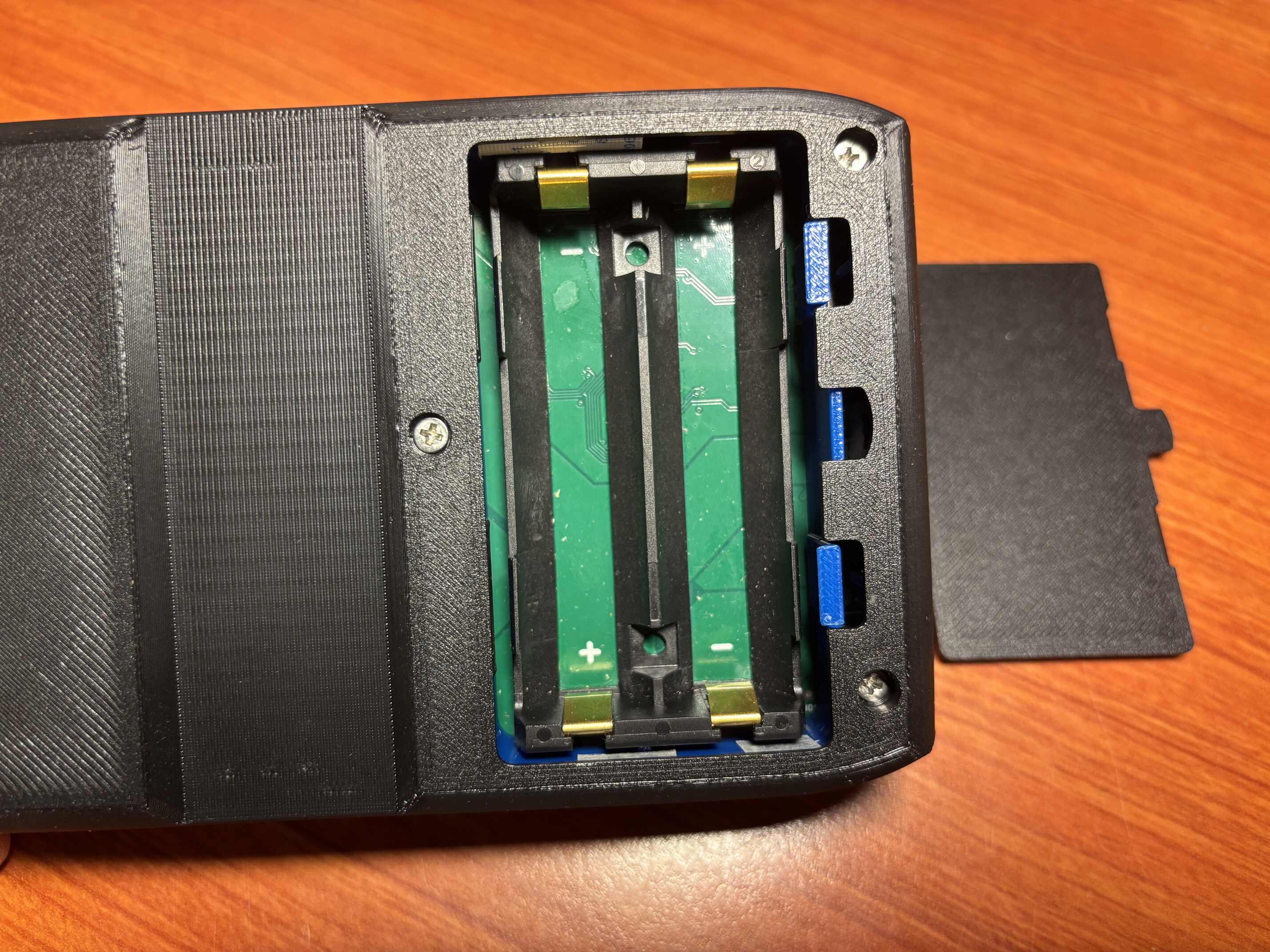
- 10,000 mAh (2×21700) or 7,000 mAh (2×18650) 2S battery pack as the main power source.
- Supports USB-PD chargers for up to 2 A fast charging and device power.
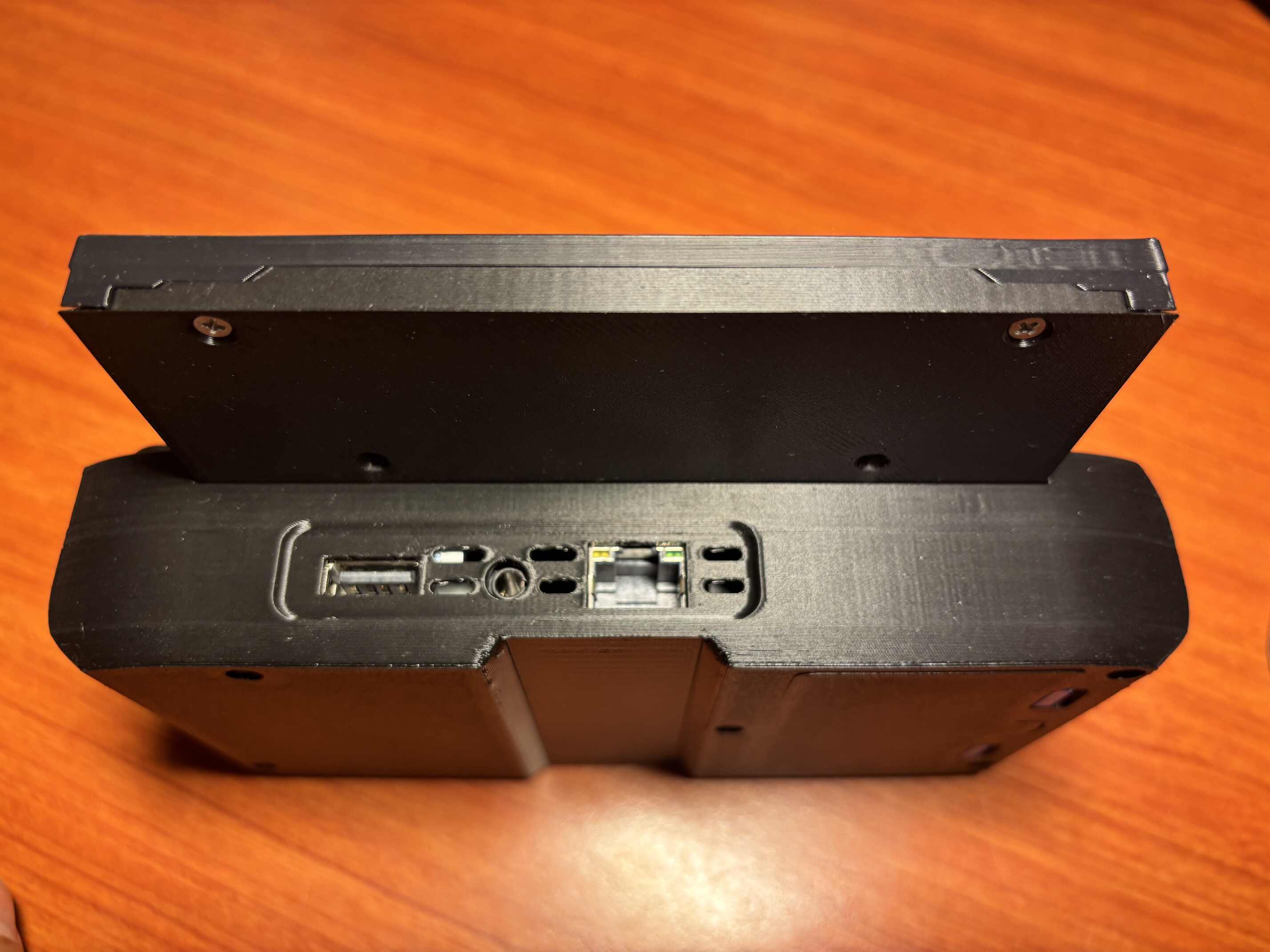
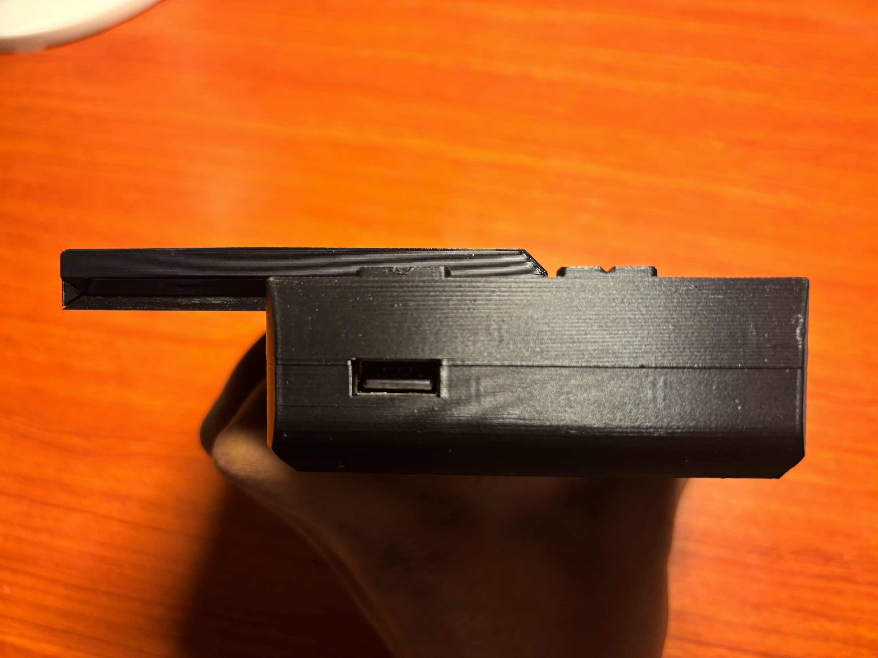
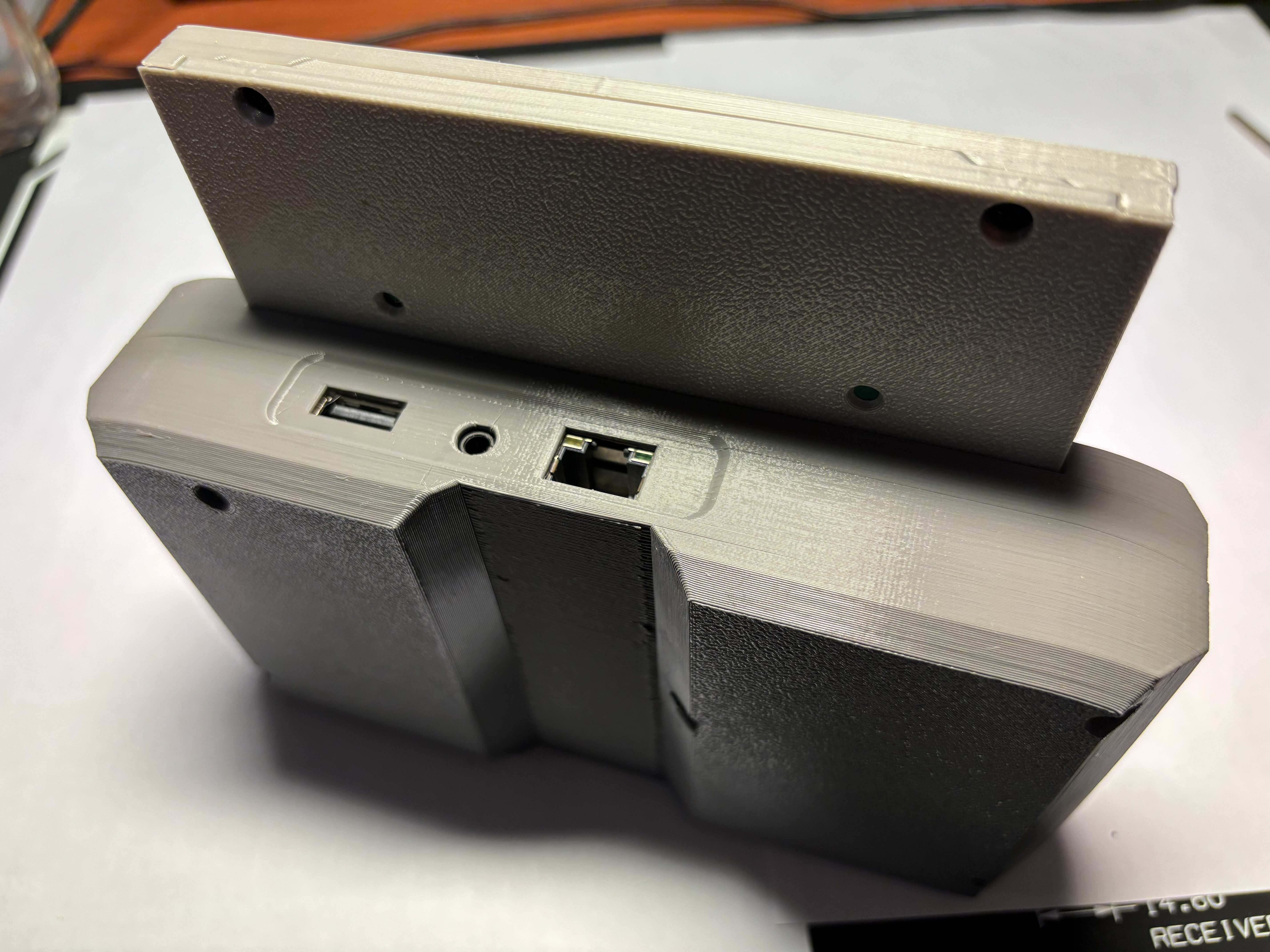
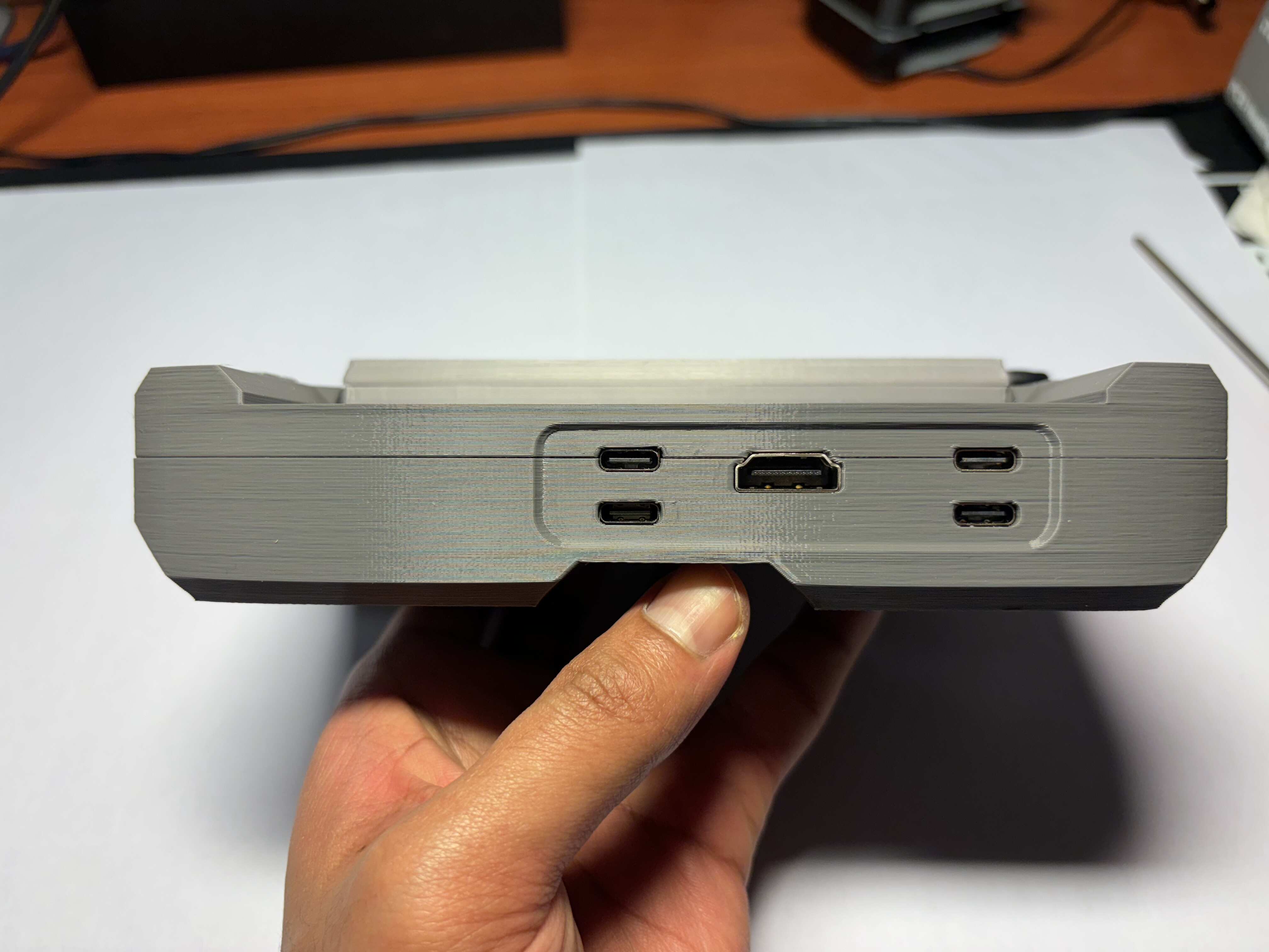
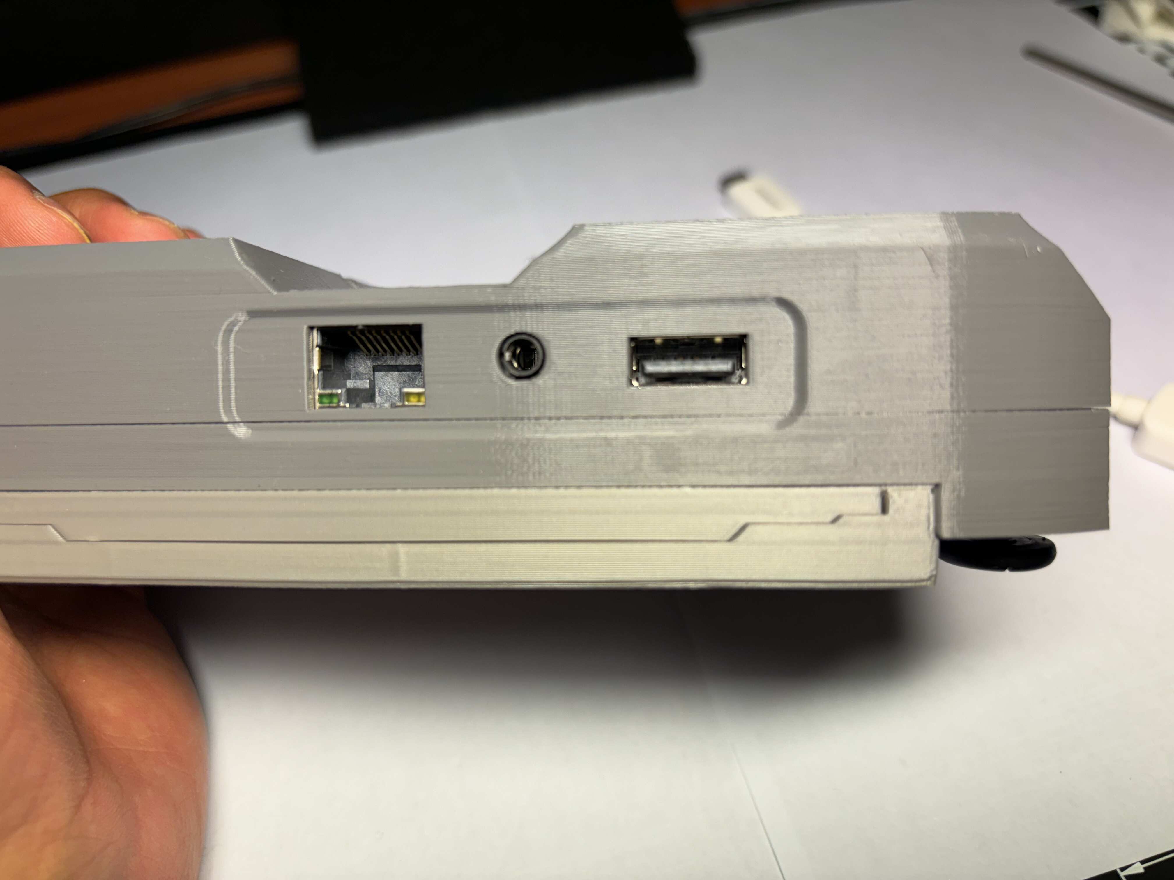
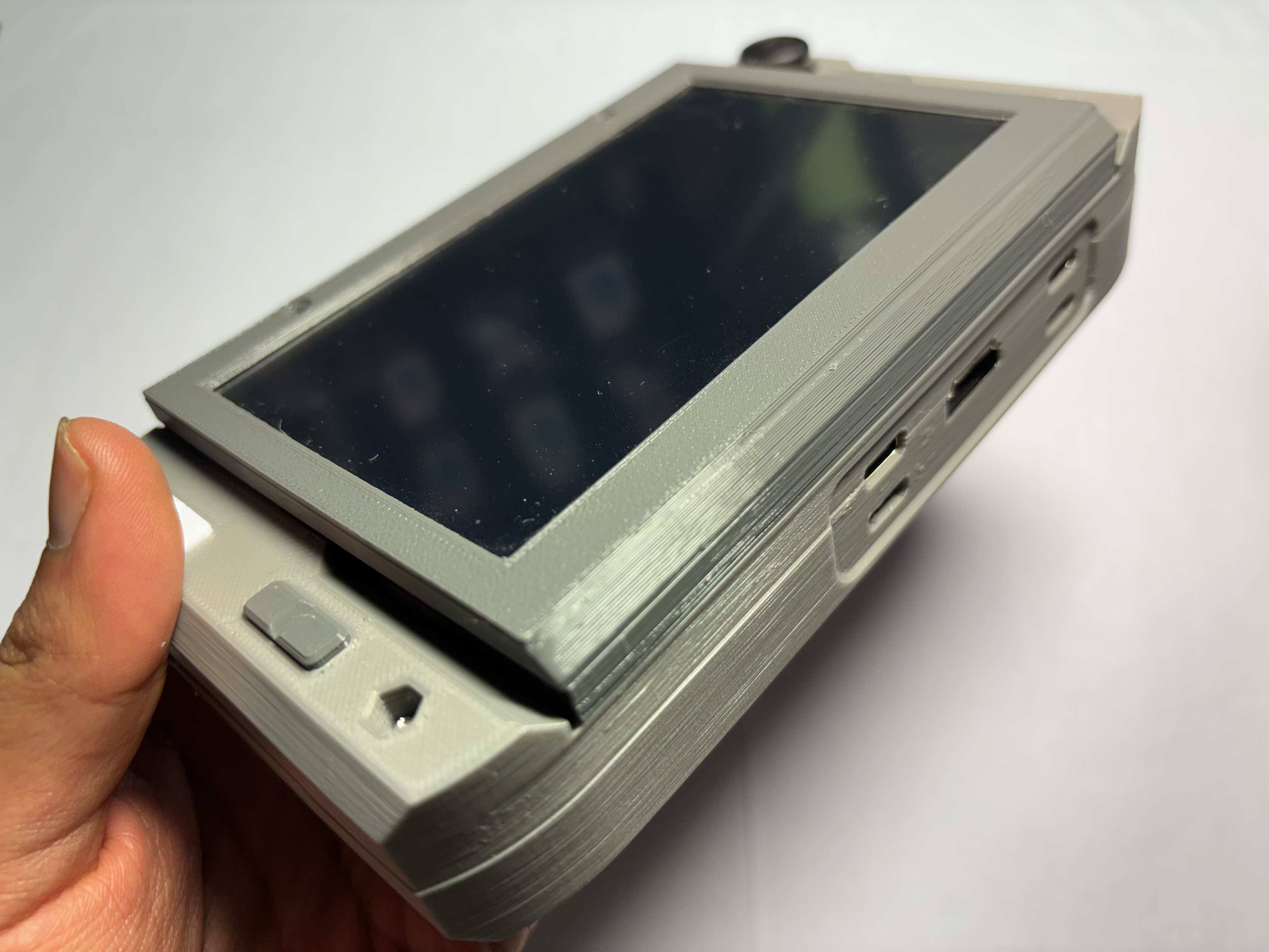
- One USB-A port and one external display output.
- USB-C form-factor Nurolink/docking port with UART and I2C.
- Additional features available via add-on boards.
- Supports full power-off via the OS or a keyboard key.
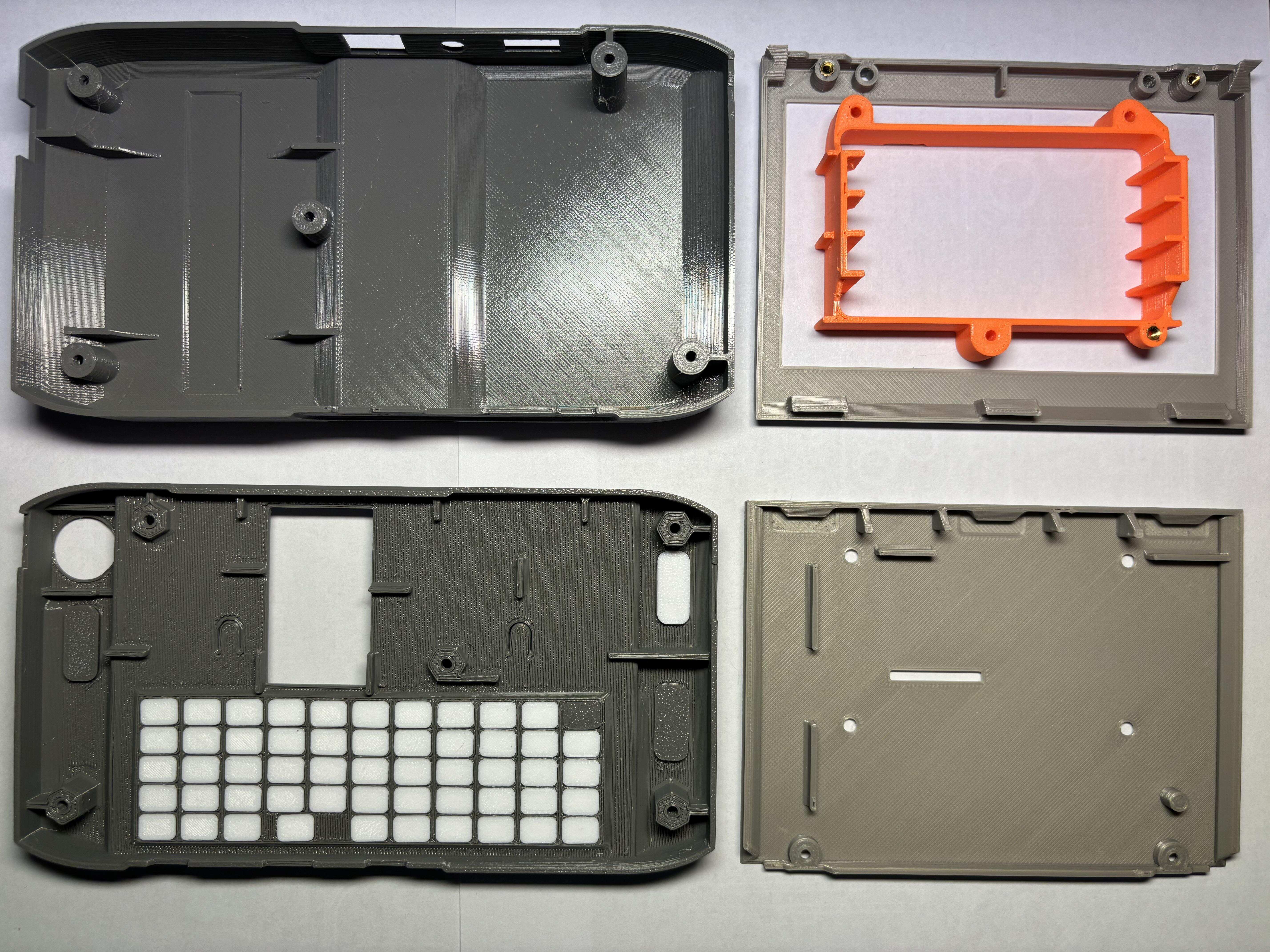
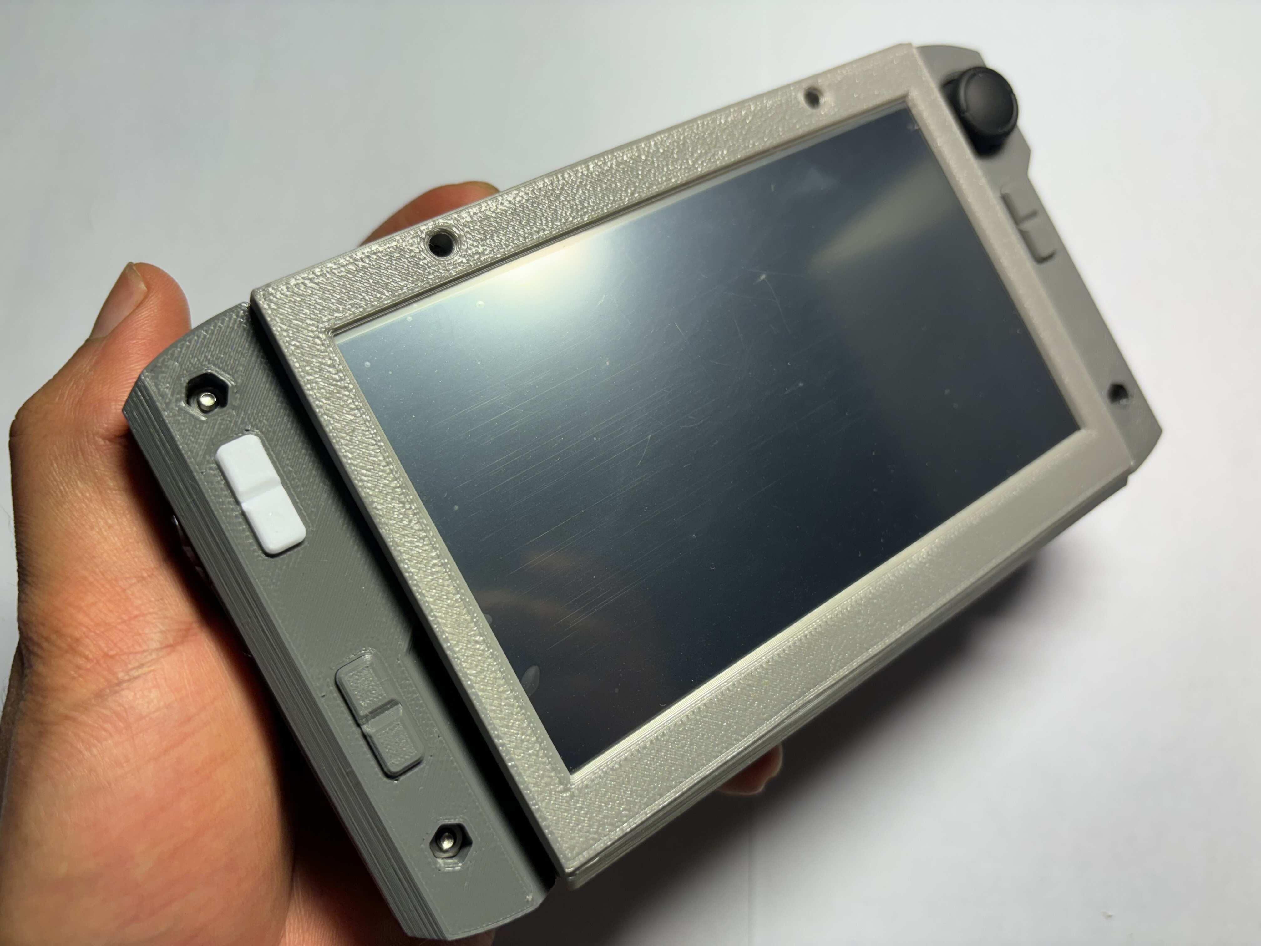
- Improved casing for cleaner prints and better fit compared to v4.
Comparison
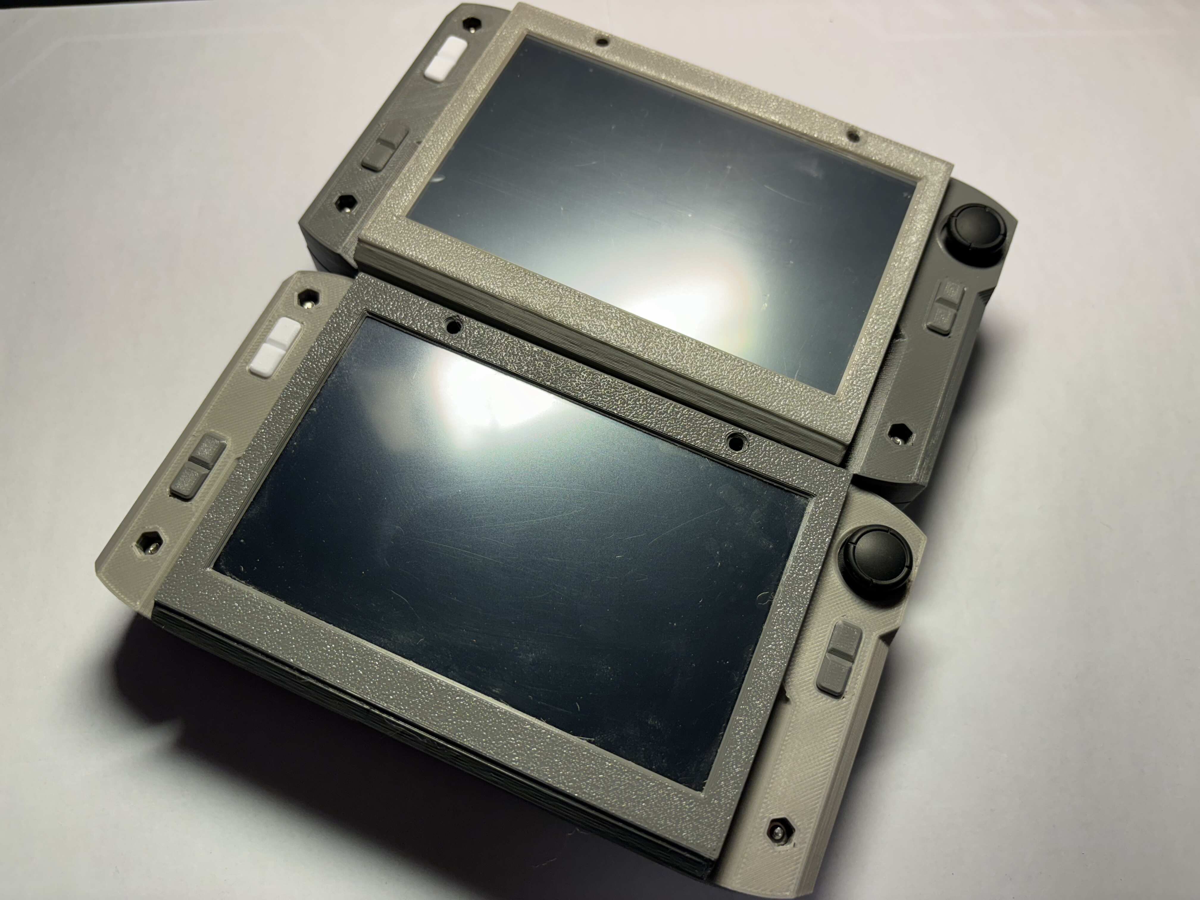
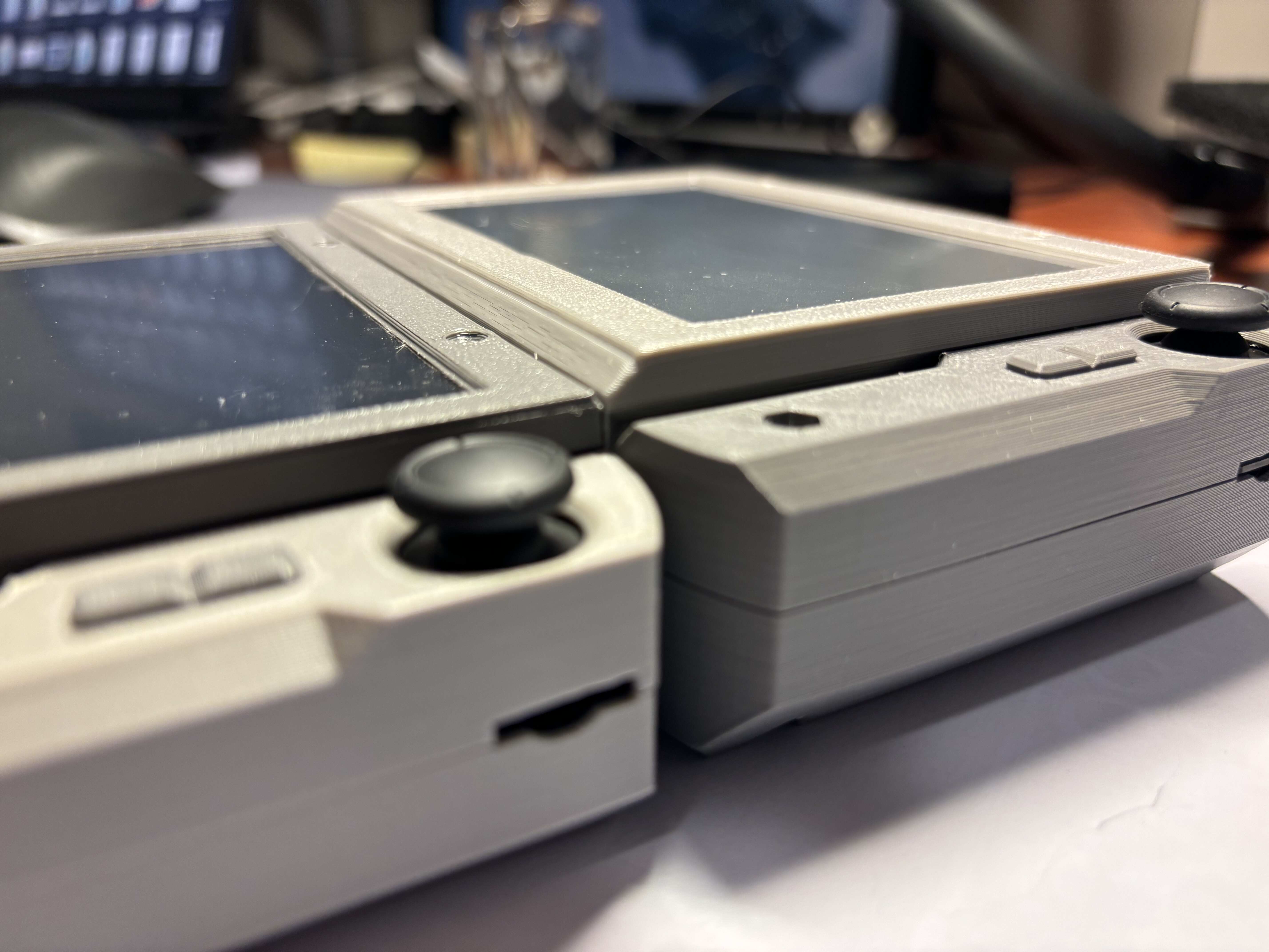
mutantC_v5 has two variants. Choose based on portability and desired battery capacity. See this comparison table to decide which one to build.
| Features | Regular | Extended Battery |
|---|---|---|
| Battery type | 7000mAh(2x18650) | 10000mAh(2x21700) |
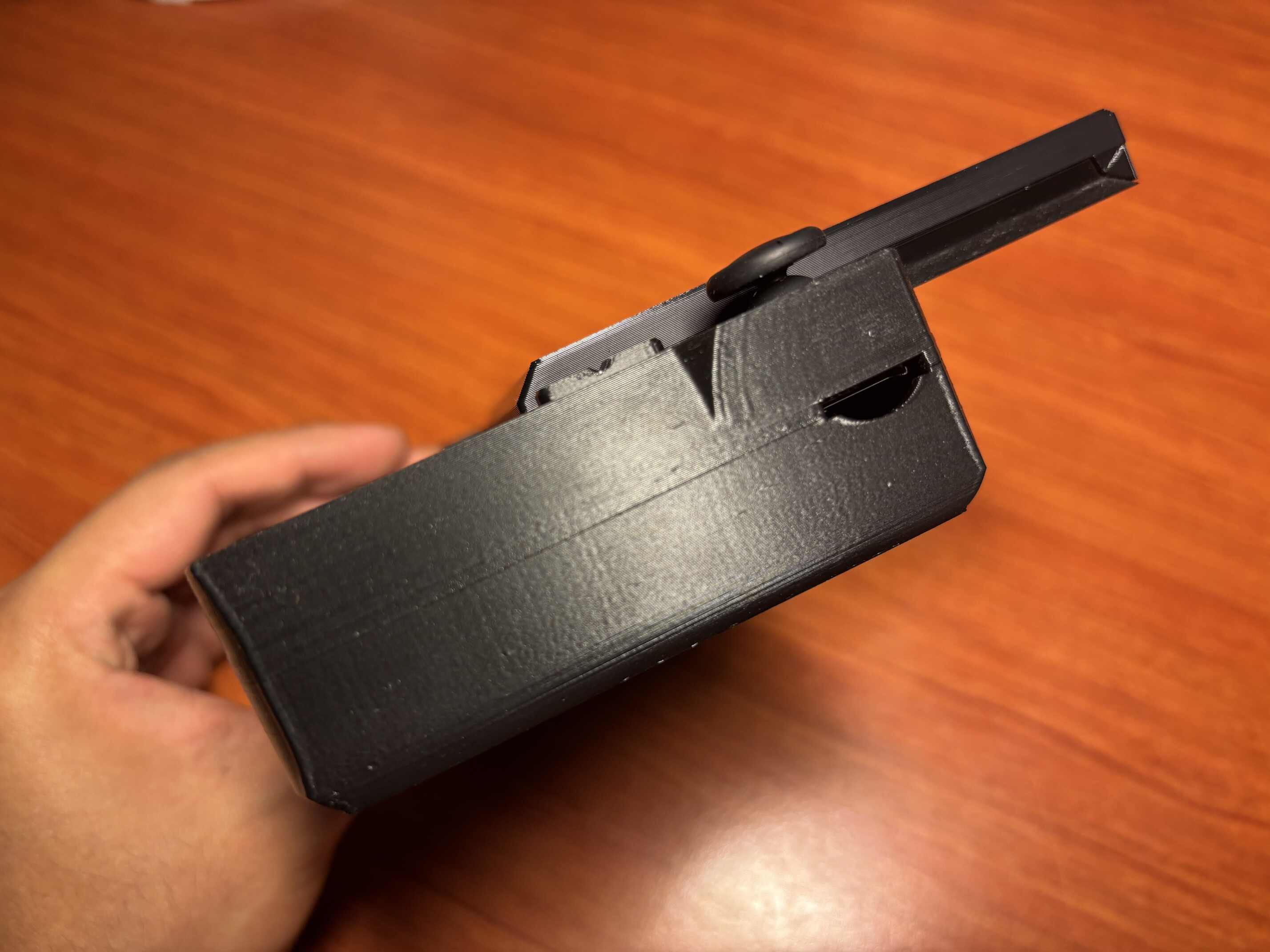
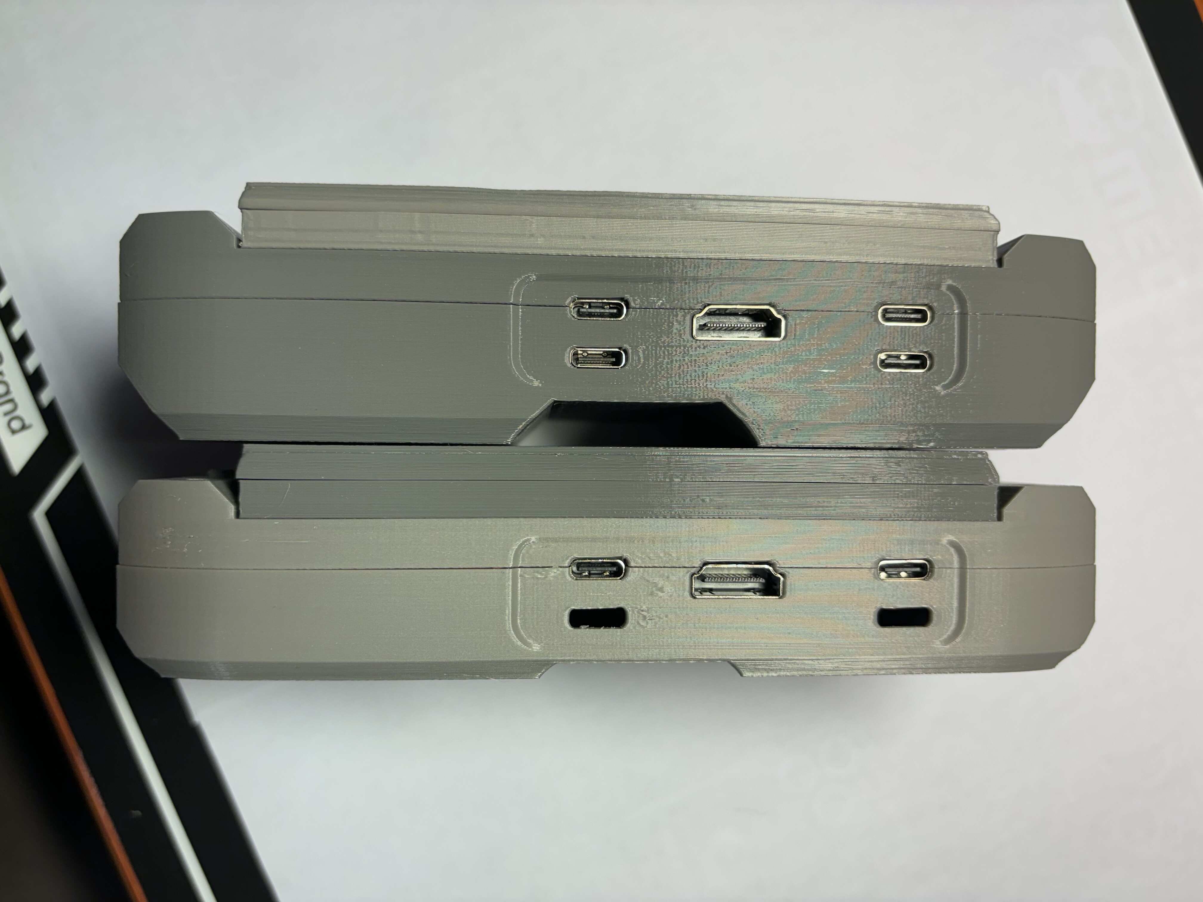
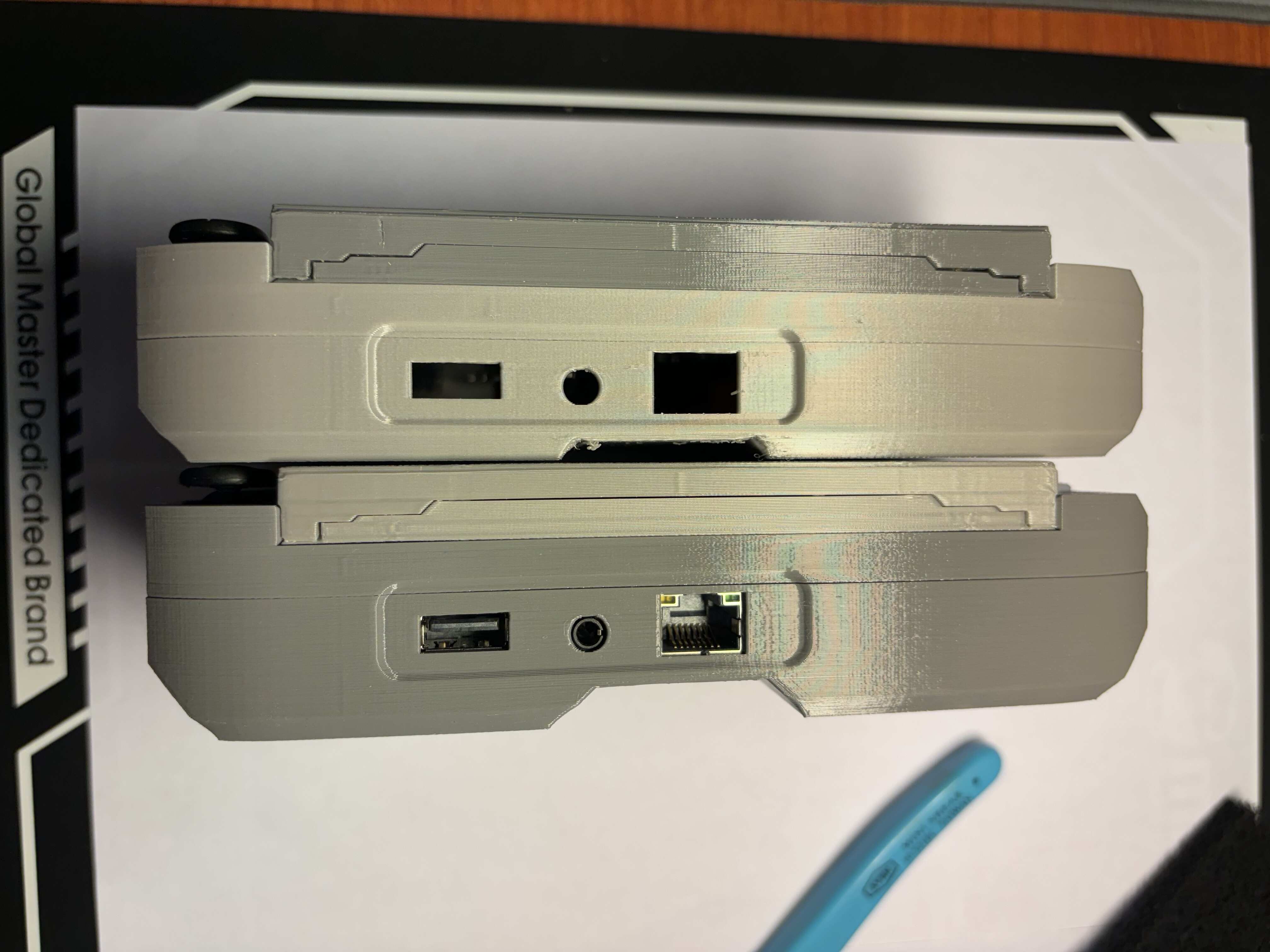
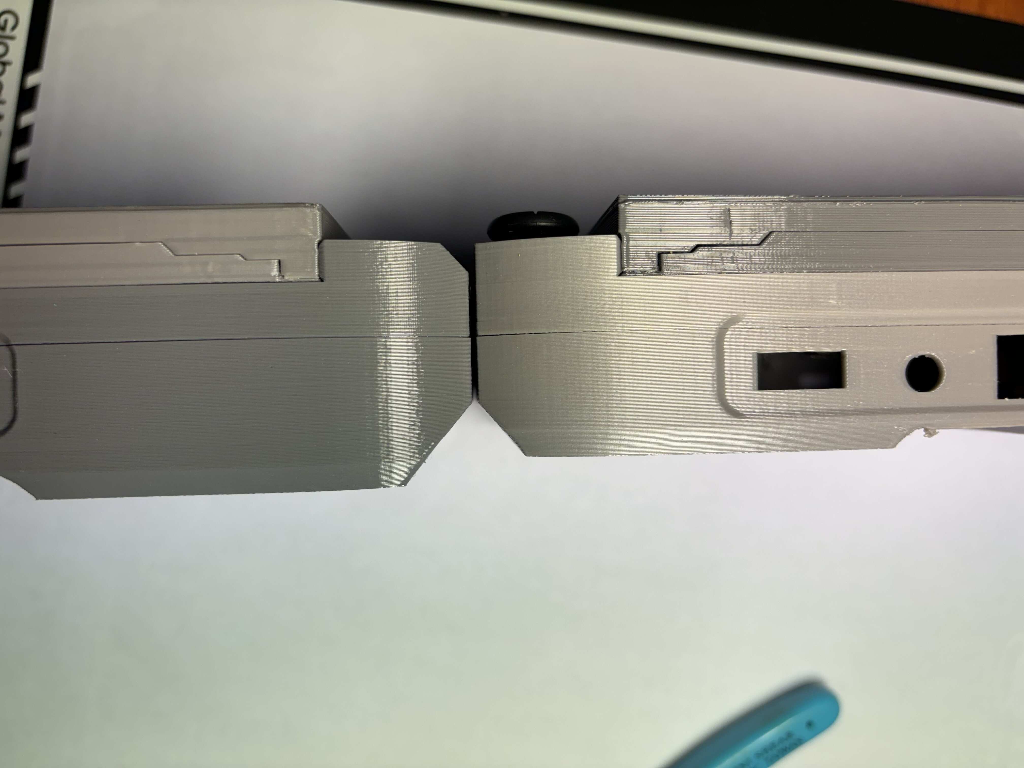
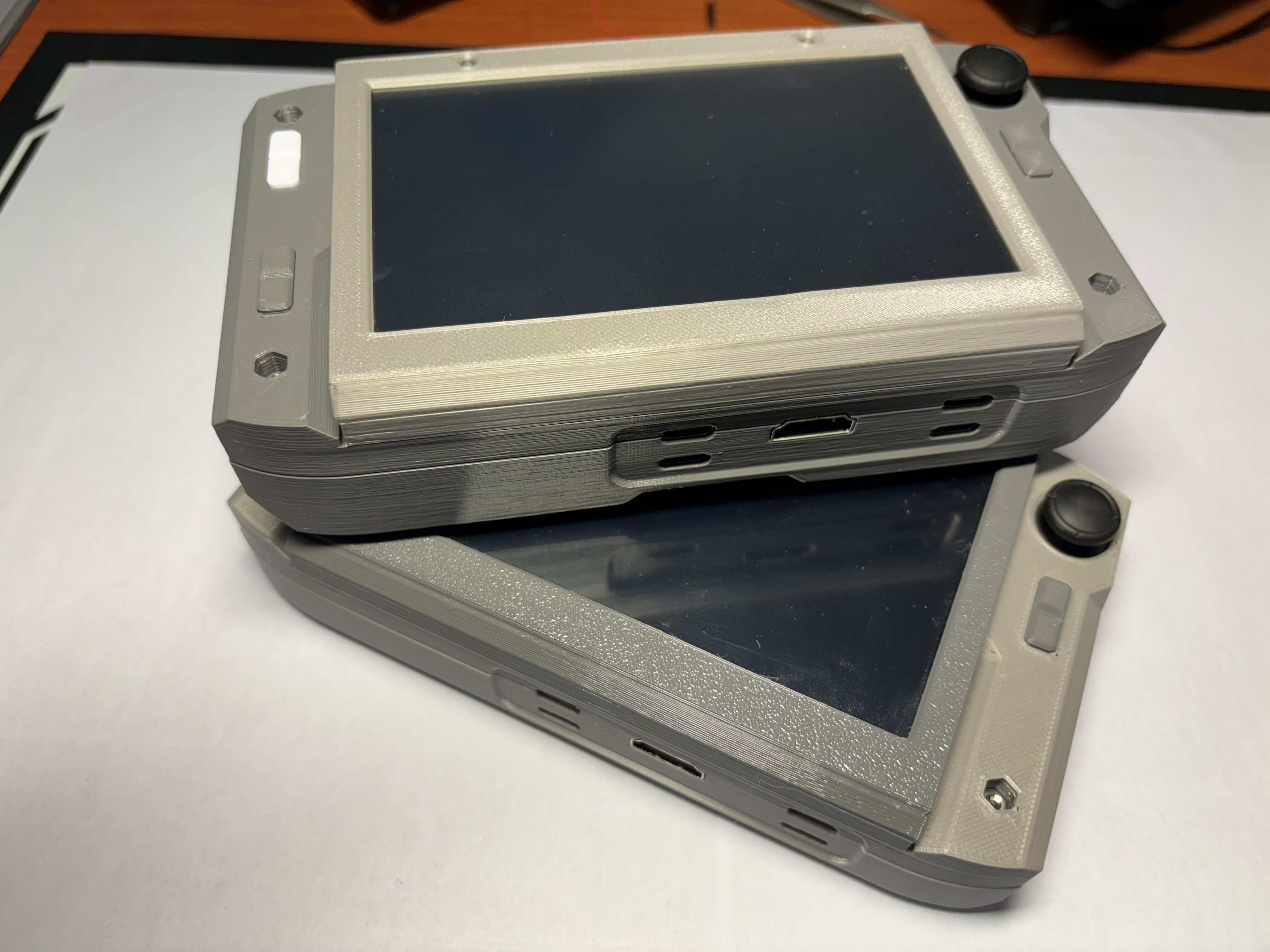
| Device Thickness | 39mm | 42mm |
| Battery Life | To be tested | To be tested |
Build Guide
Warning: Repository source files may not reflect a stable build and could fail if used as-is. Use this build guide for a reliable build; it always references verified working files.
Build guide for mutantC v5.1 – Instructables.
For the latest stable release, all 3D parts, PCBs, device firmware, and source files are on GitLab and free to download and use.
- Source link for mutantC v5.1 - GitLab.
- mainPCB BOM v5.1- Interactive BOM.
- displayPCB BOM v5.1- Interactive BOM.
For upcoming releases:
- Source link for mutantC v5.2 - WIP.
- mainPCB BOM v5.2 - WIP.
- displayPCB BOM v5.2 - WIP.
Add-On Support
mutantC_v5 supports add-on boards for additional features. Add-ons use the 50-pin FPC connector which provides GPIO, USB, PCIe, Ethernet, and power.
- Apollo Add-on - Source.
- USB-C form factor Nurolink+/docking port with UART, I2C, SPI, GPIO.
- Additionally, USB-A, USB-C, audio out, and Ethernet can be added with the Apollo add-on board.
- Full-size 2280 M.2 SSD can be added with the add-on board.
- Reads battery level and powers off the device when the battery is low.
PCB Feature Blocks
The PCB silkscreen lists numbered blocks. Each block provides one or more features. To enable a feature, populate all components in that block. Below is the list of blocks.
| Main PCB | |||
|---|---|---|---|
| Blocks | Name | Feature | Priority |
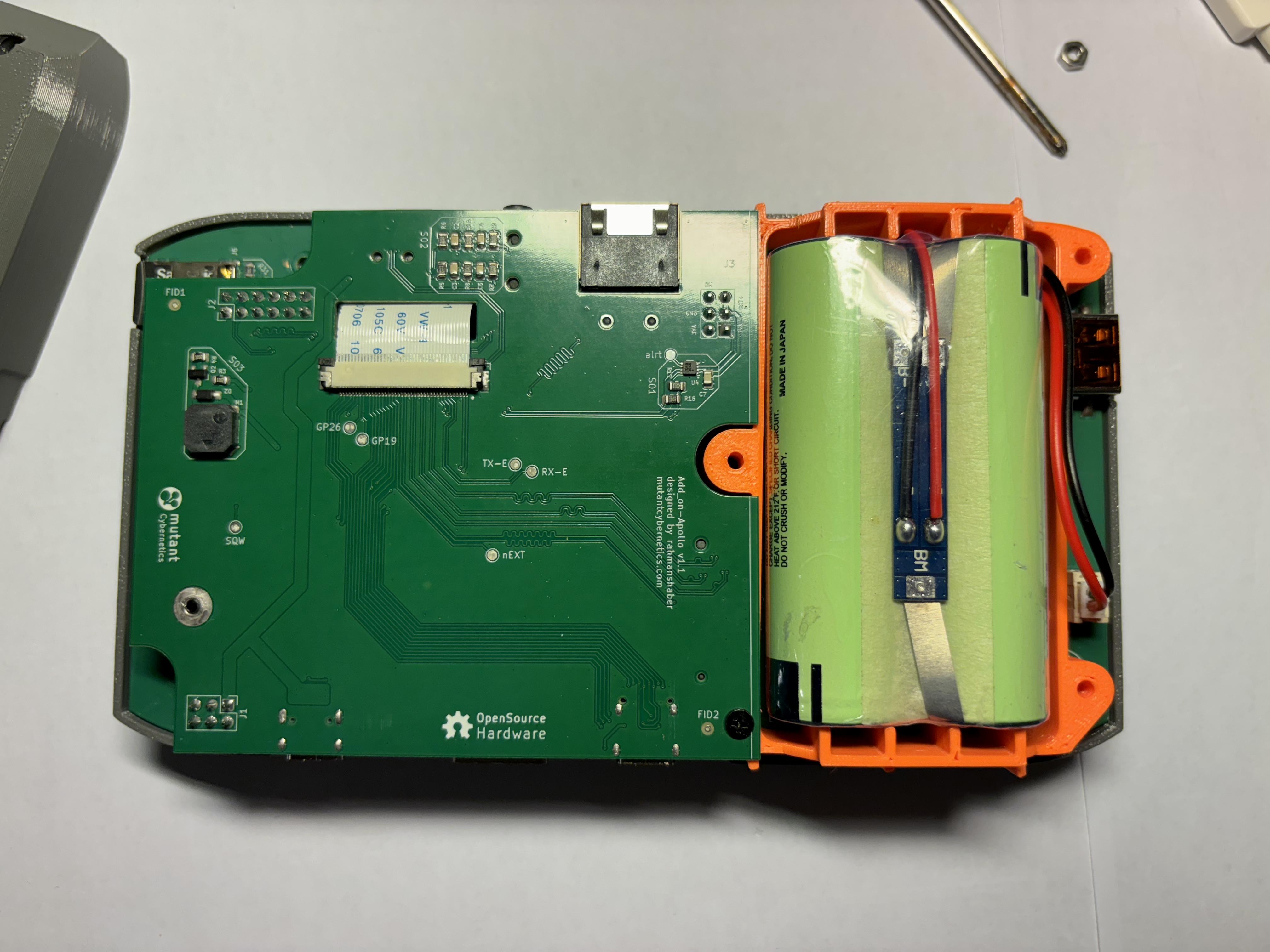
| S00 | Battery Protection | Battery protection circuit for Li-ion batteries in the holder | Required |
| S01 | USB-C PD | Use USB power delivery feature for charging and powering the device | Required |
| S02 | 2S Battery Charging | Charging circuit for the 2S battery | Required |
| S03 | Power Switch | Switching between battery or power-in and turning on/off the device | Required |
| S04 | 5V Voltage Regulator | 5V buck converter for SBC, USB, HDMI and add-ons | Required |
| S05 | 3.3V Voltage Regulator | 3.3V buck converter for ESP32, USB hub IC, and add-ons | Required |
| S06 | ESP32 Microcontroller | Controls peripherals such as the keyboard and mouse | Required |
| S07 | 4-Port USB HUB | Uses one USB from the SBC and provides four USB 2.0 ports | Required |
| S08 | Compute Module | Heart of the device | Required |
| S09 | CM Activity & Power LED | Shows compute module's activity and power state | Optional |
| S10 | SD-Card Power | Powers the SD card; omit if the SBC has eMMC storage | Optional |
| S11 | Ex-Display EDID Power | Power the EDID EEPROM in the external display | Required |
| S12 | Internal Display EDID | EEPROM to store the internal display size info | Optional |
| S13 | Nurolink I2C Pull-ups | Pull-ups for I2C coming from the CM | Optional |
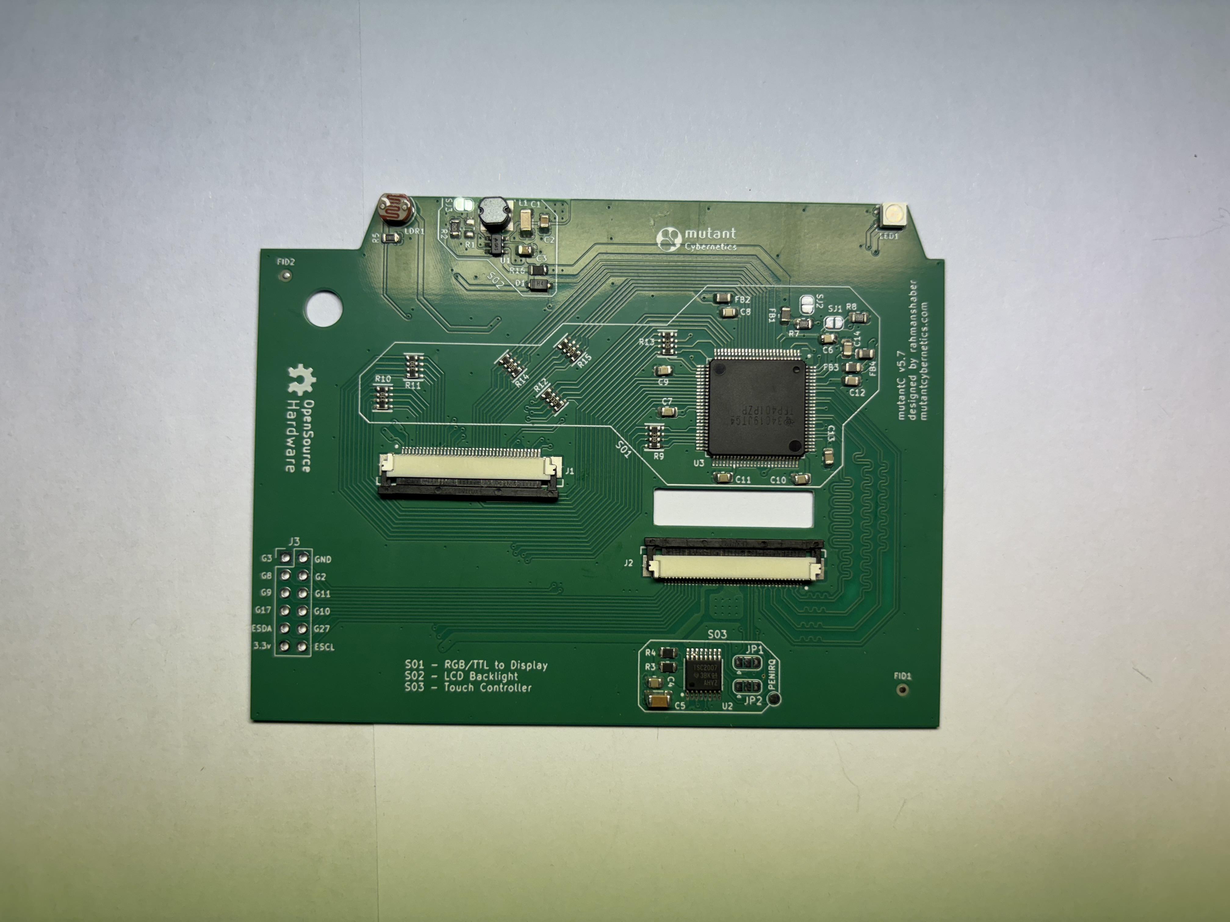
| Display PCB | |||
|---|---|---|---|
| Blocks | Name | Feature | Priority |
| S01 | RGB/TTL to Display | Converts RGB/TTL signal from the LCD into a display signal for the SBC | Required |
| S02 | LCD Backlight | Generate required voltage for LCD backlight | Required |
| S03 | Touch Controller | Converts touch input to an I2C signal; can connect to the ESP32 or SBC | Optional |
Videos
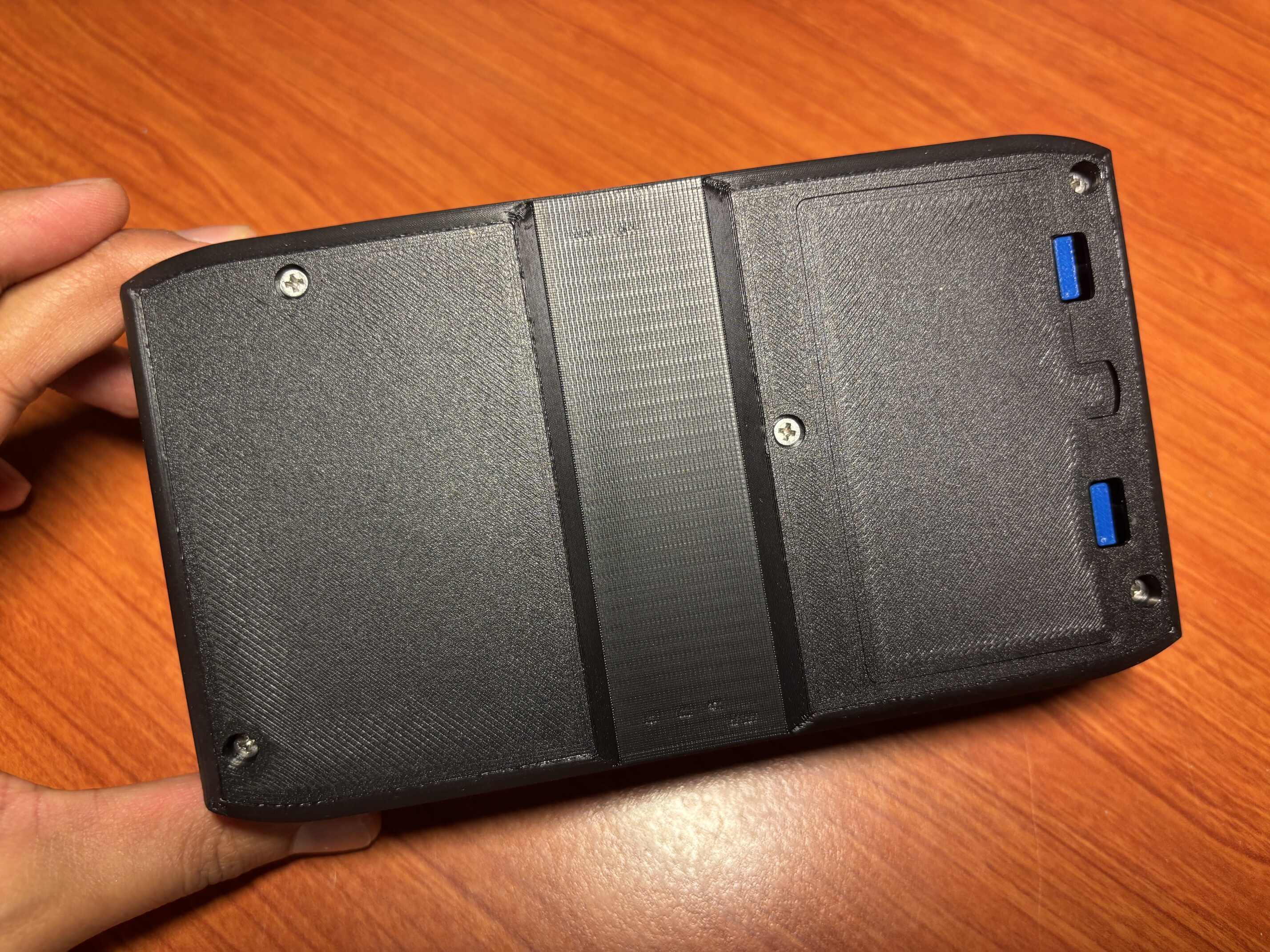
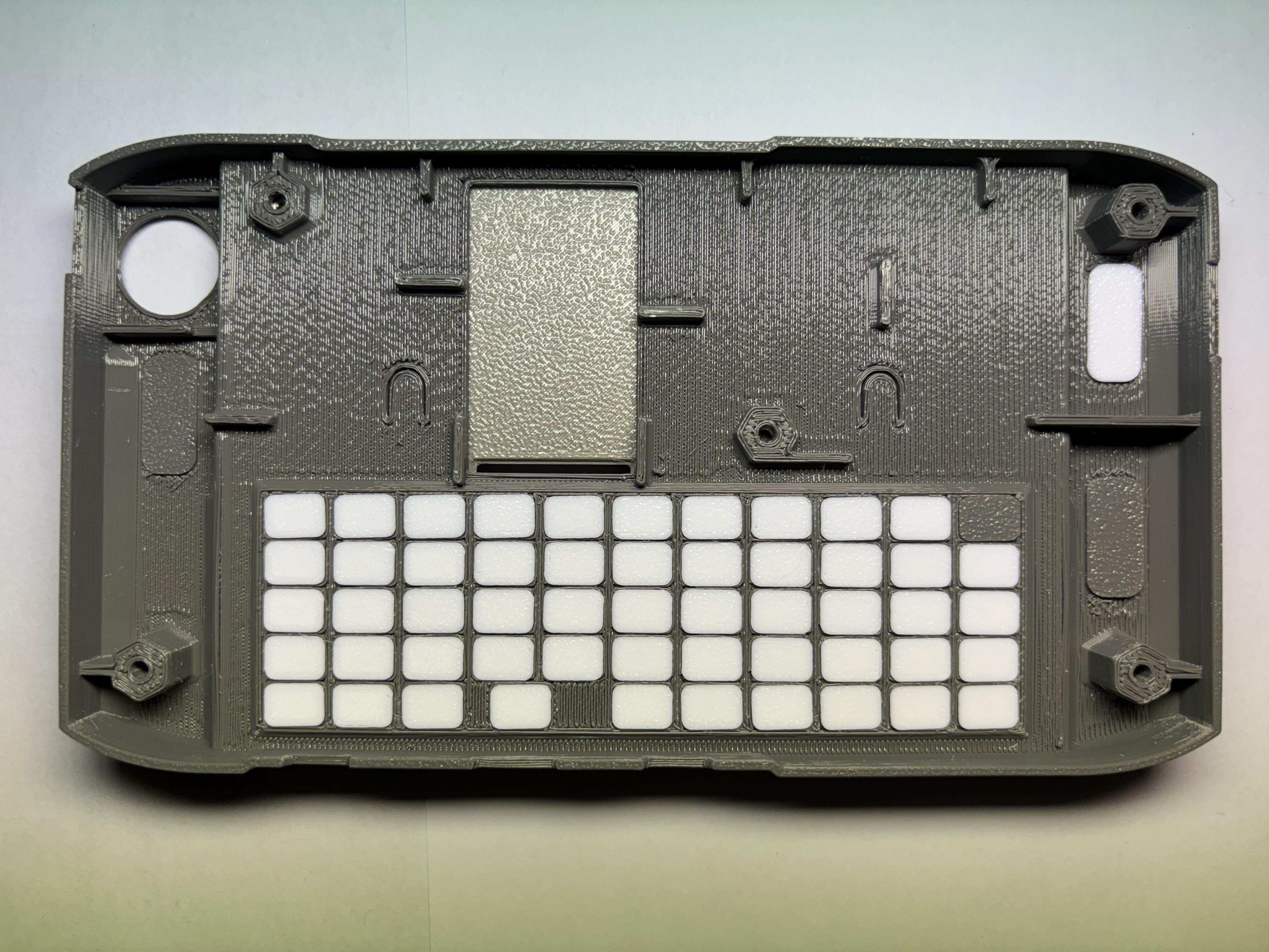
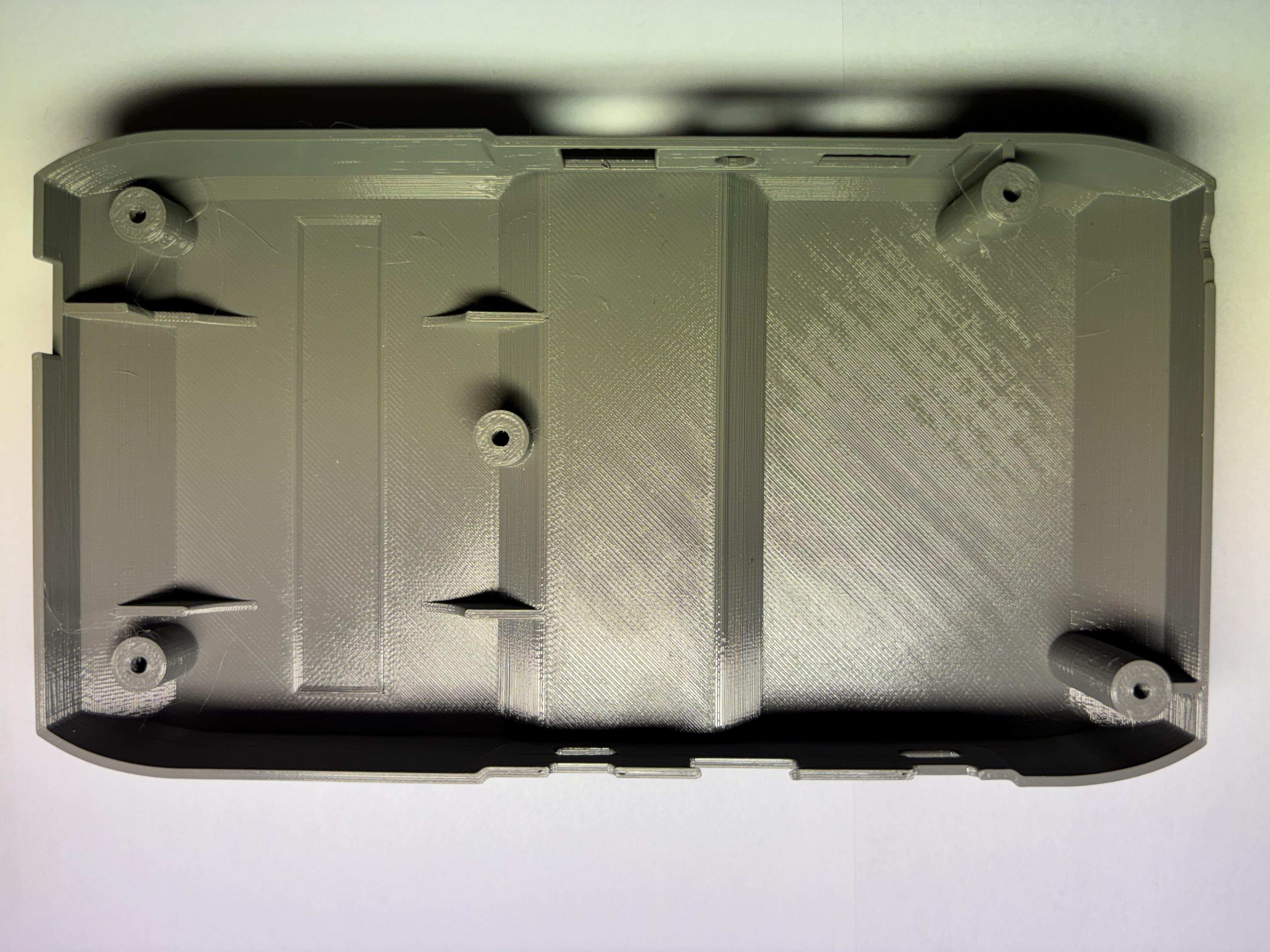
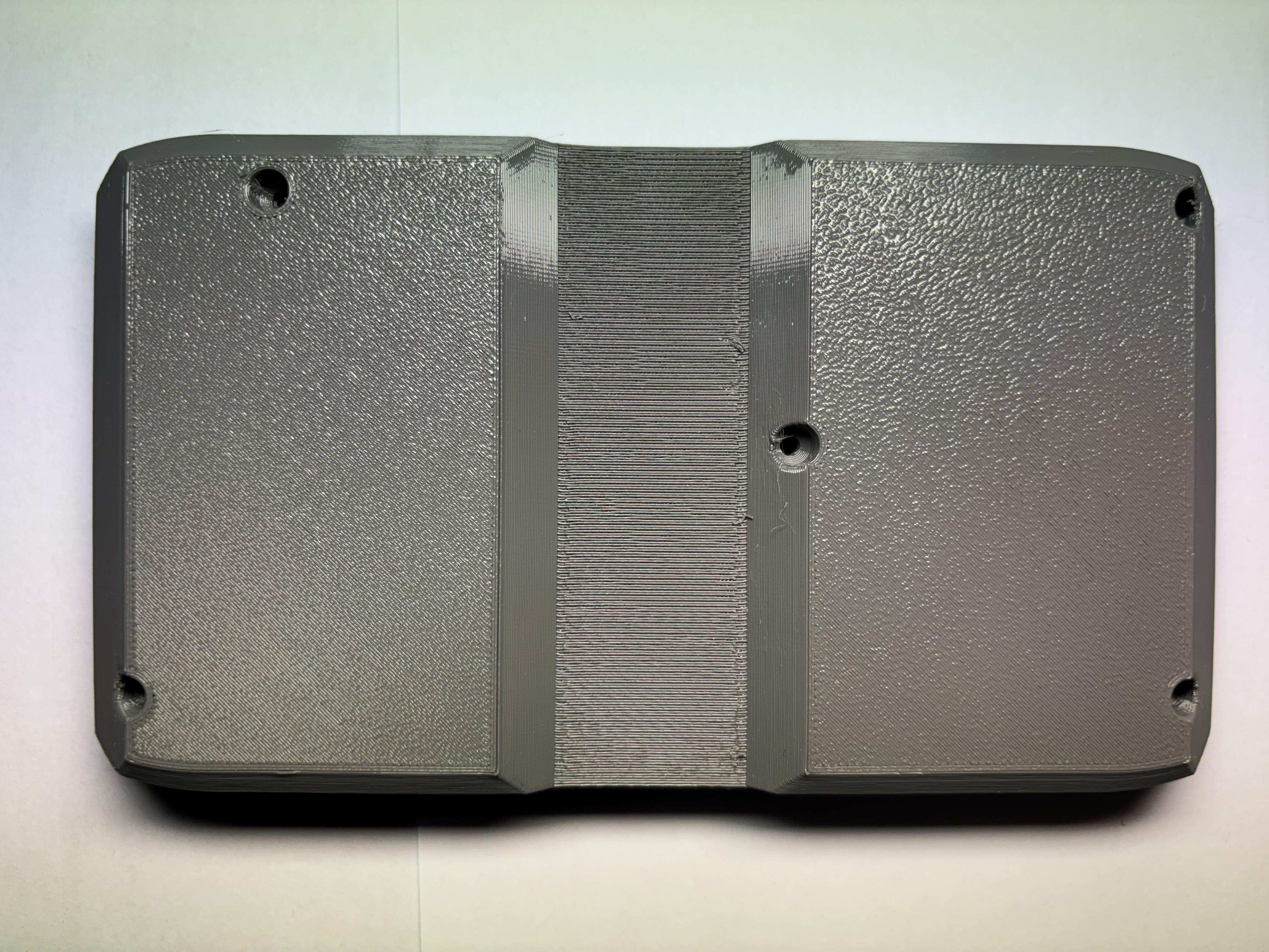
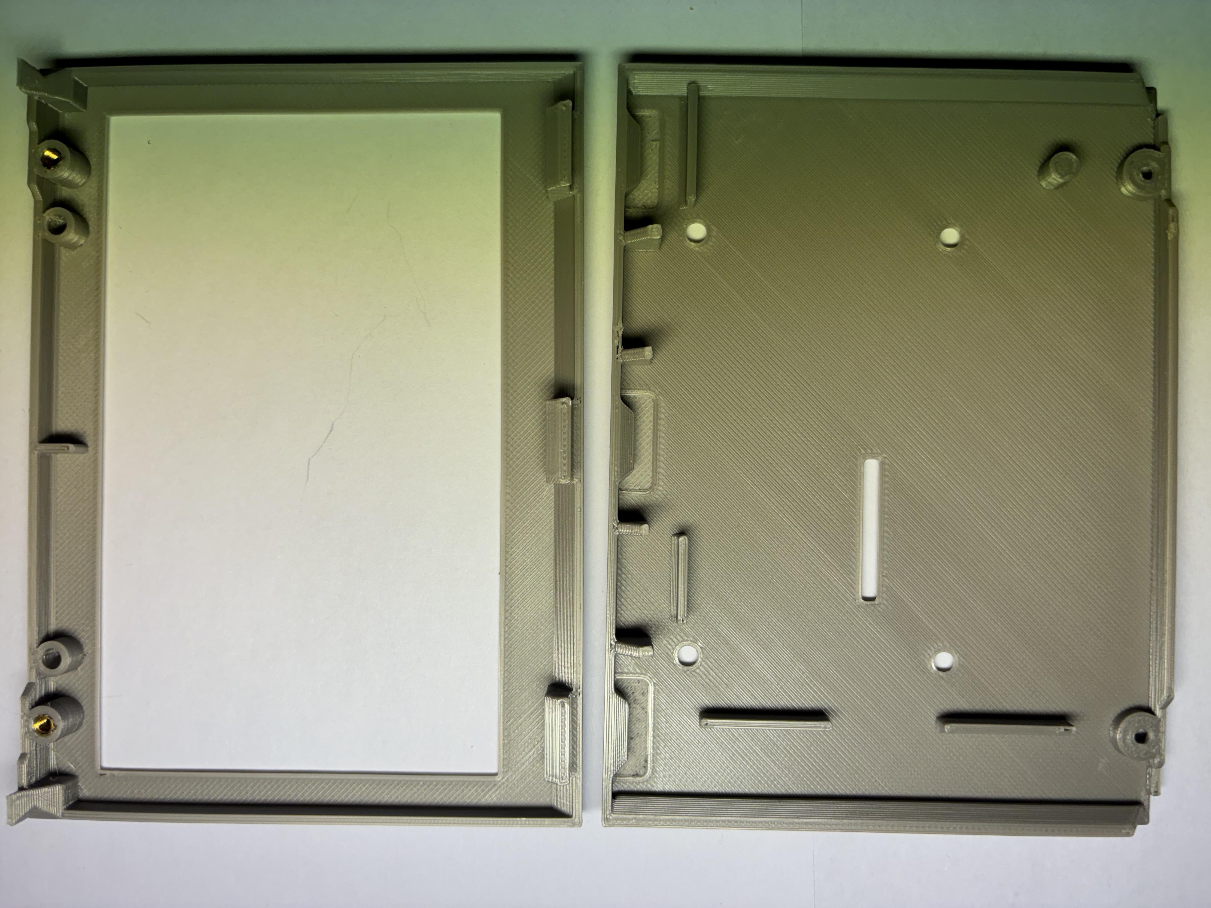
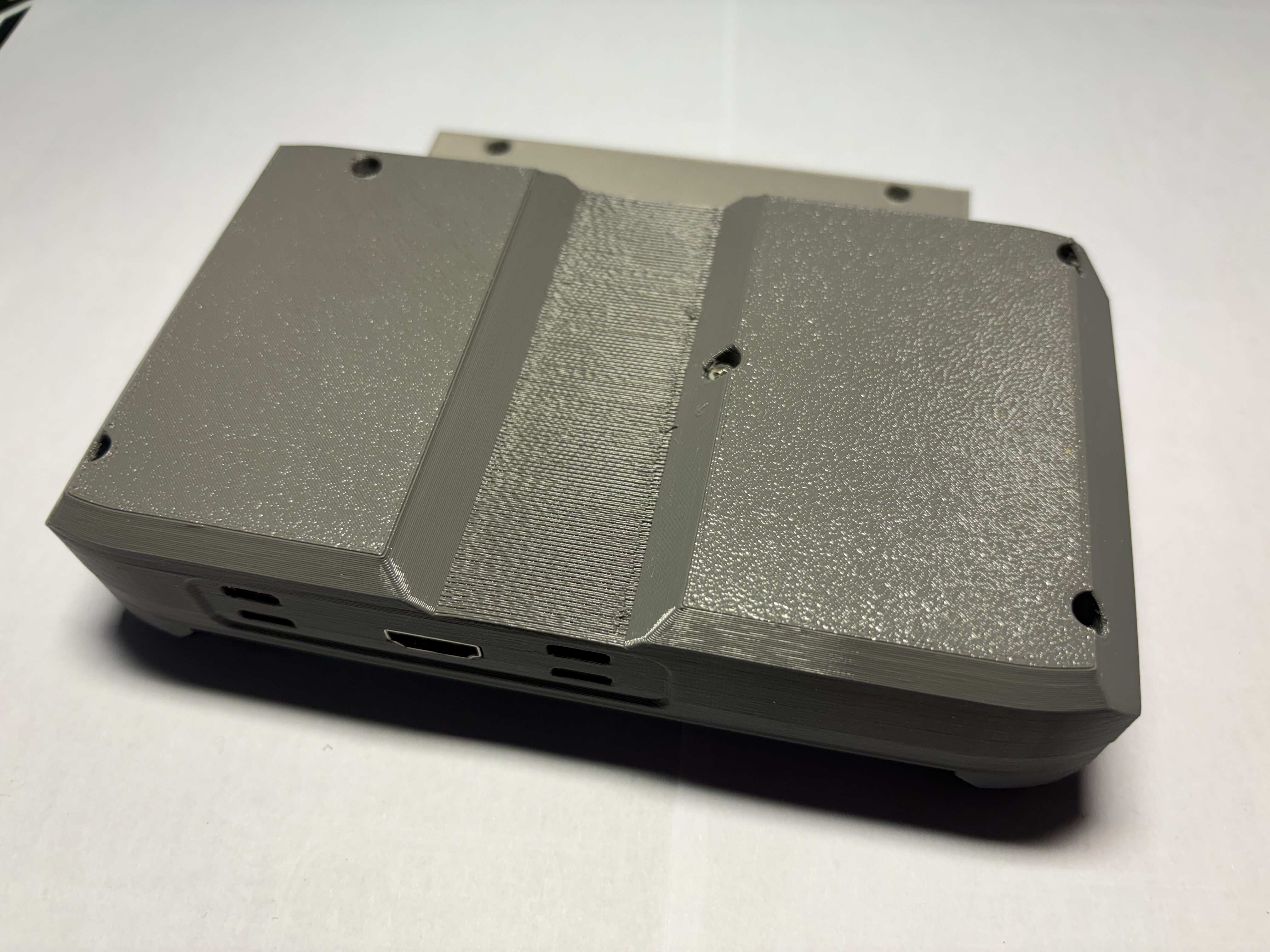
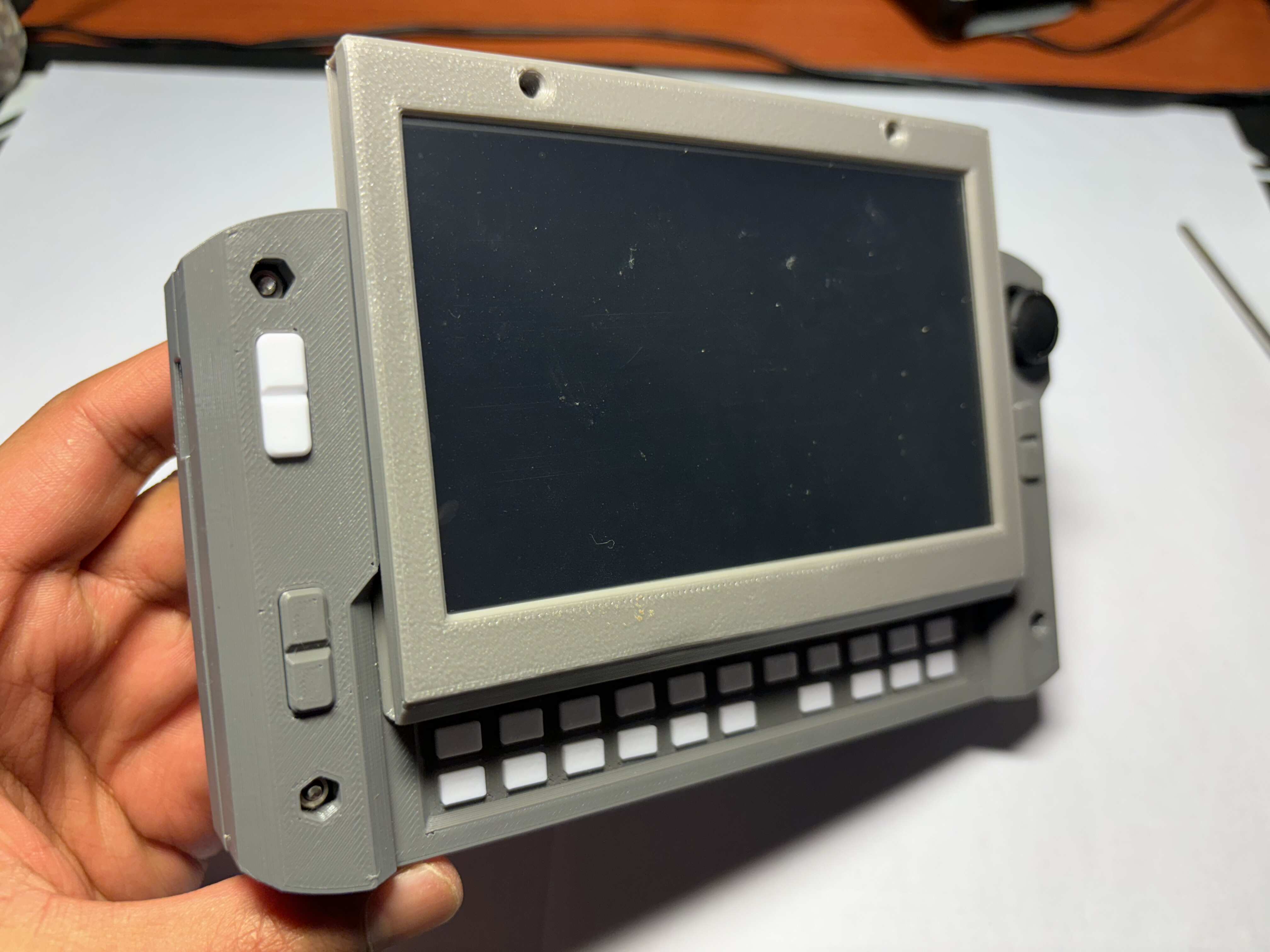
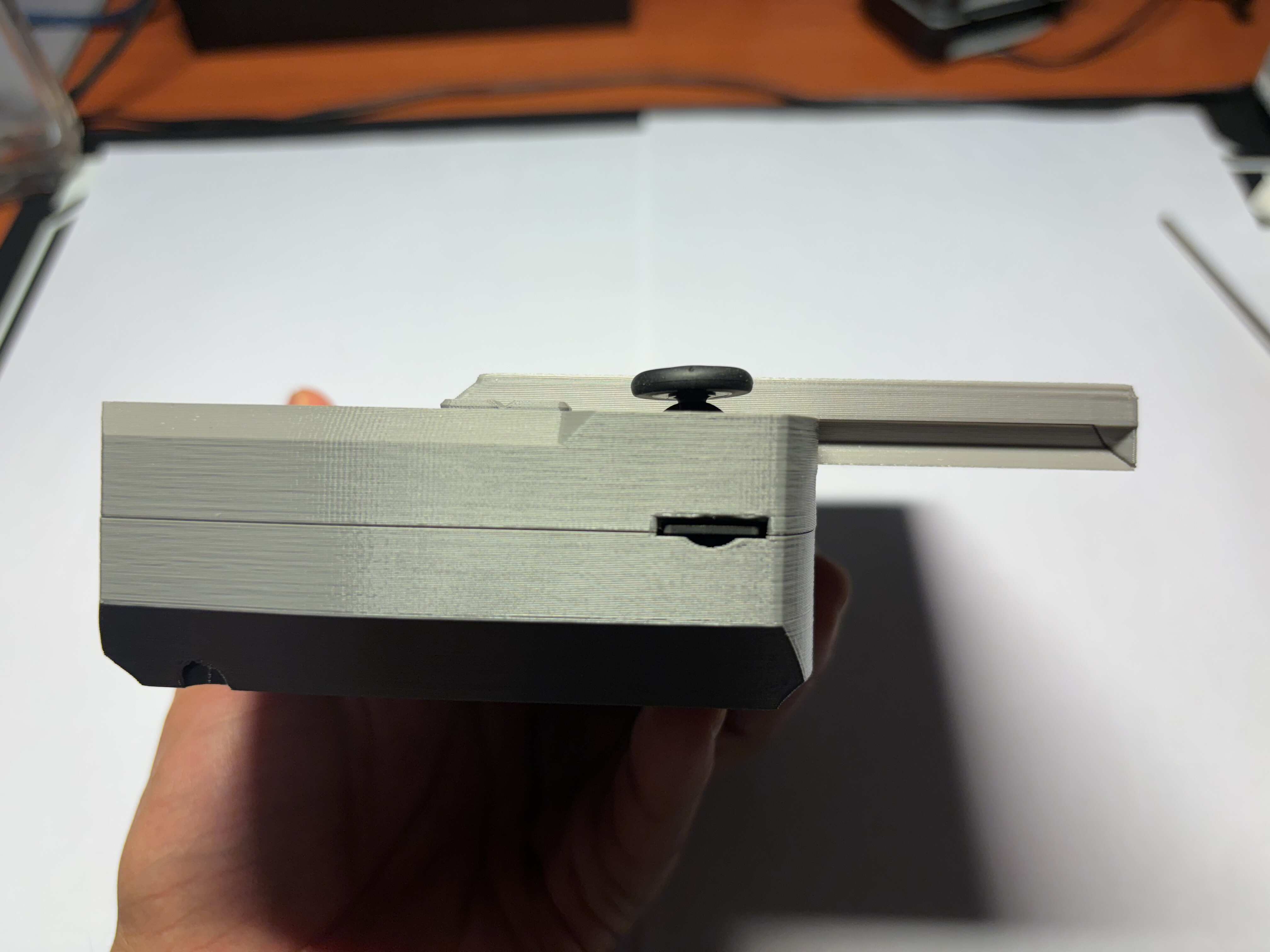
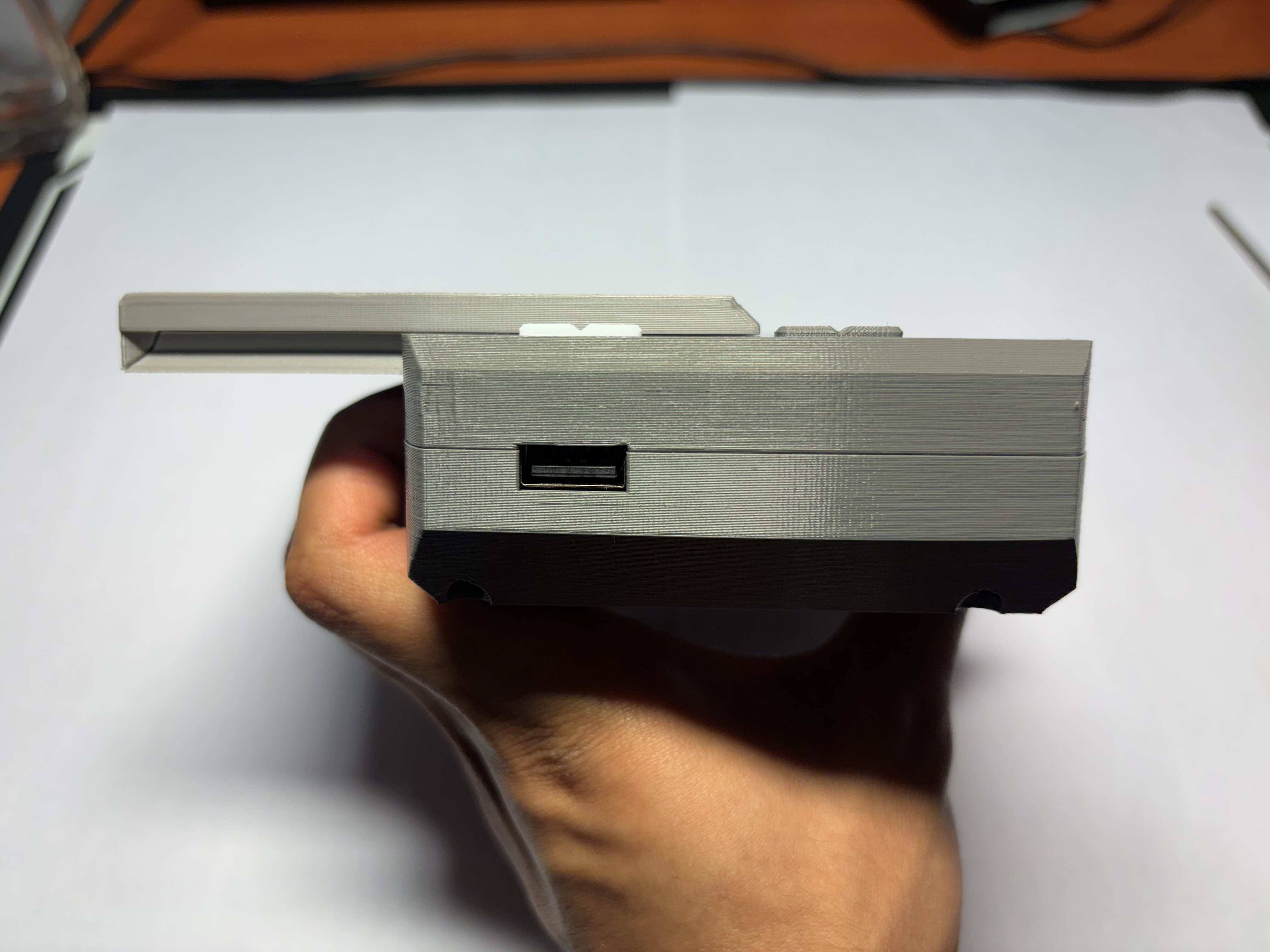
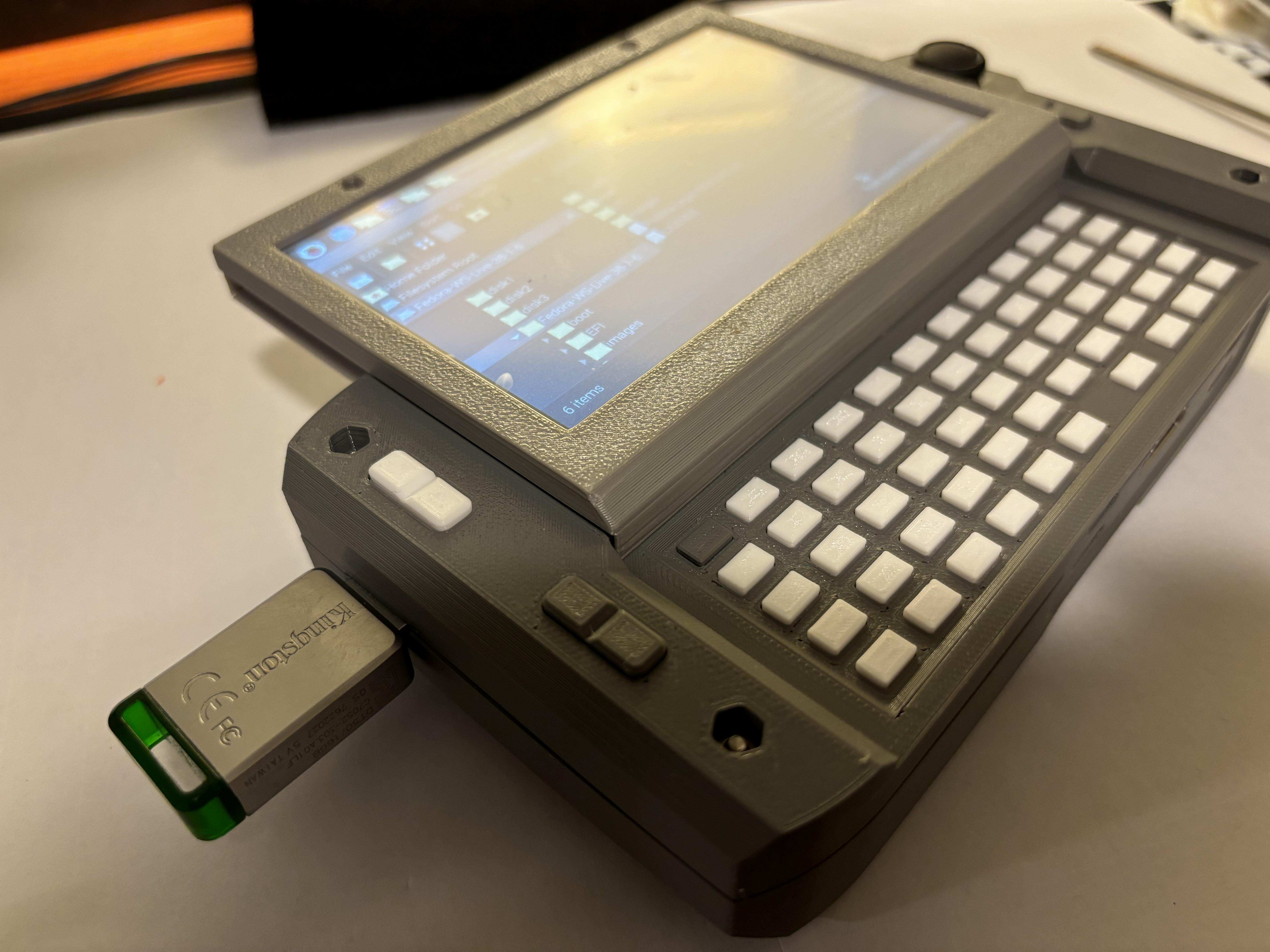
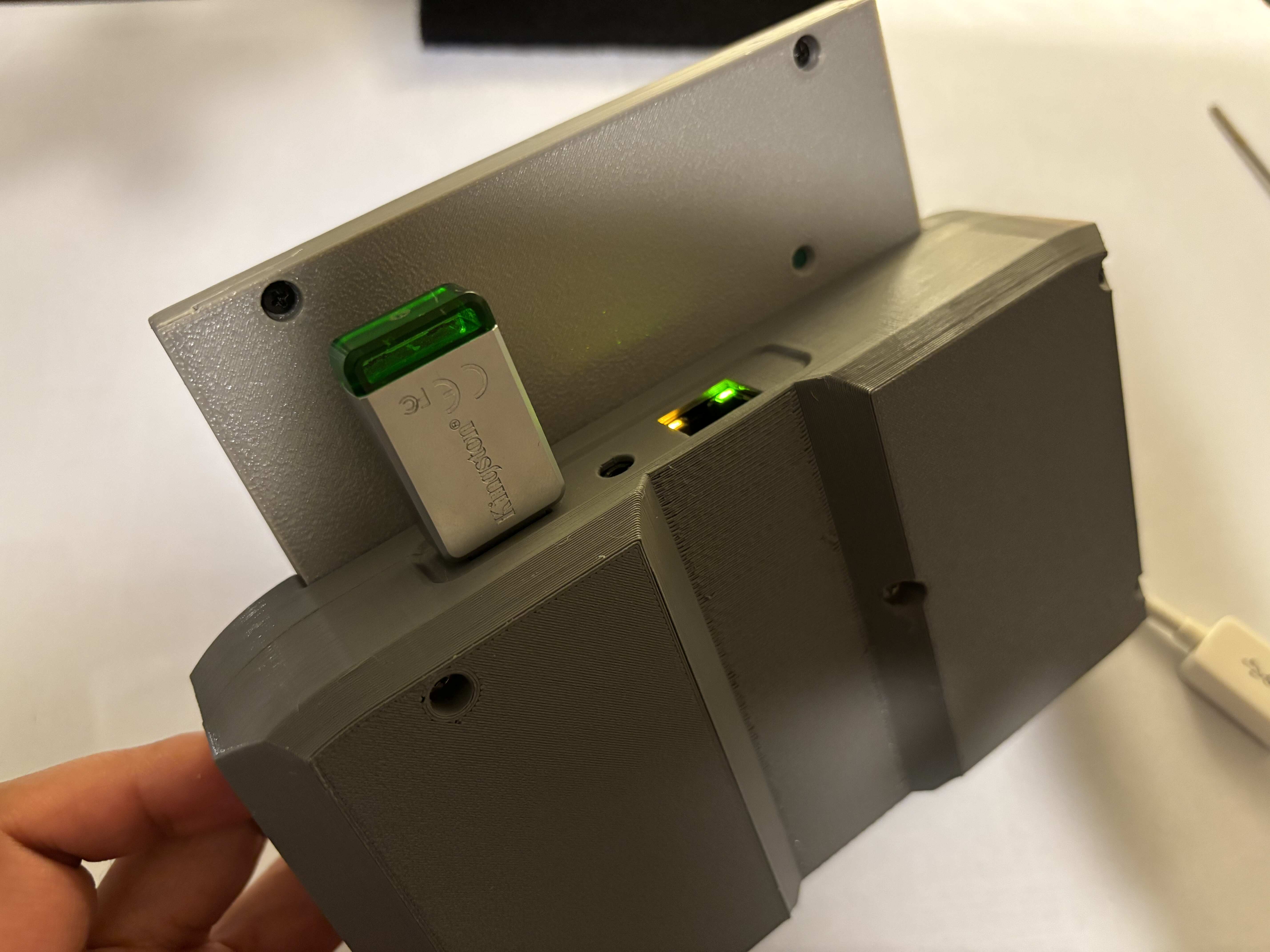
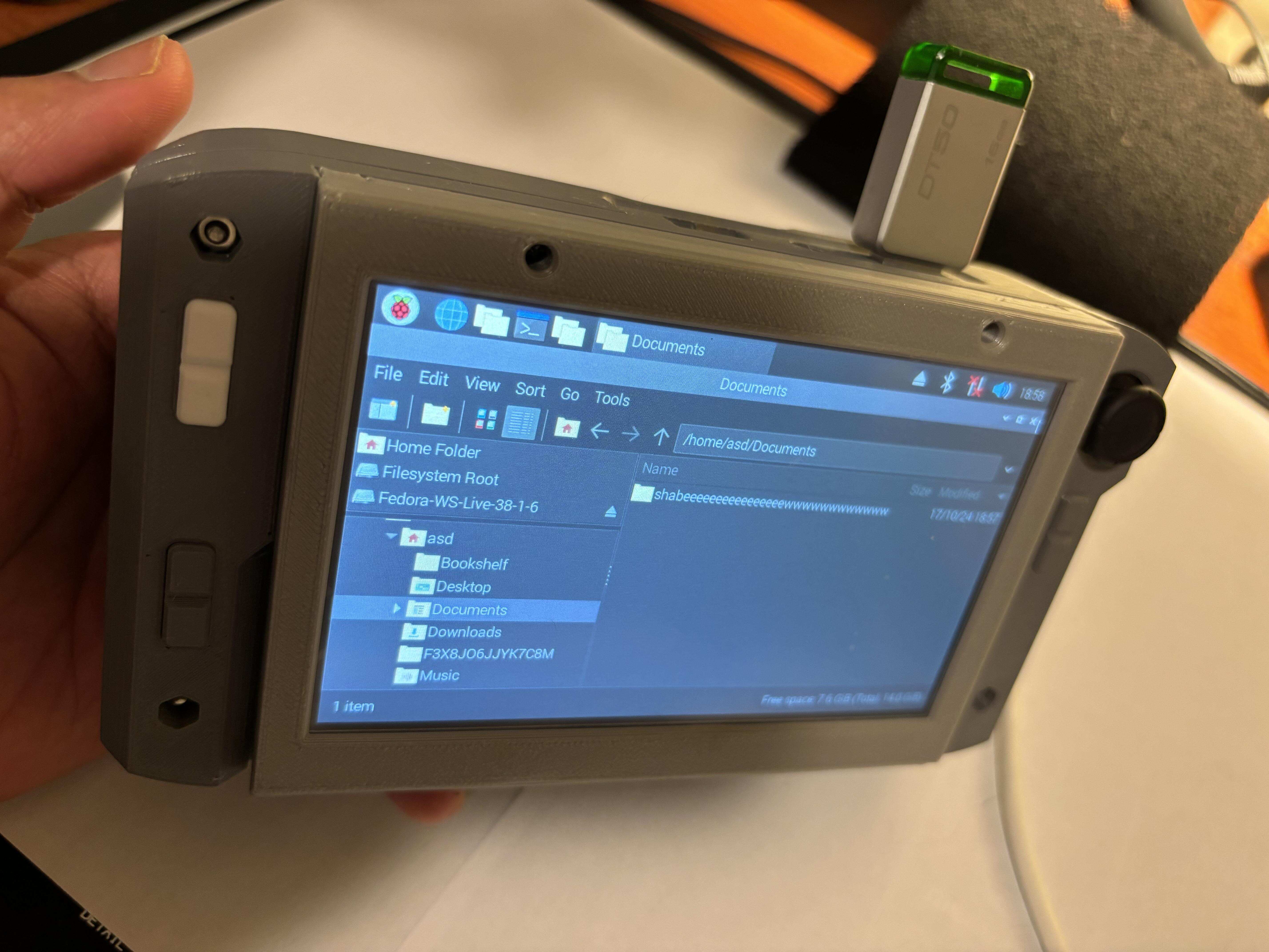
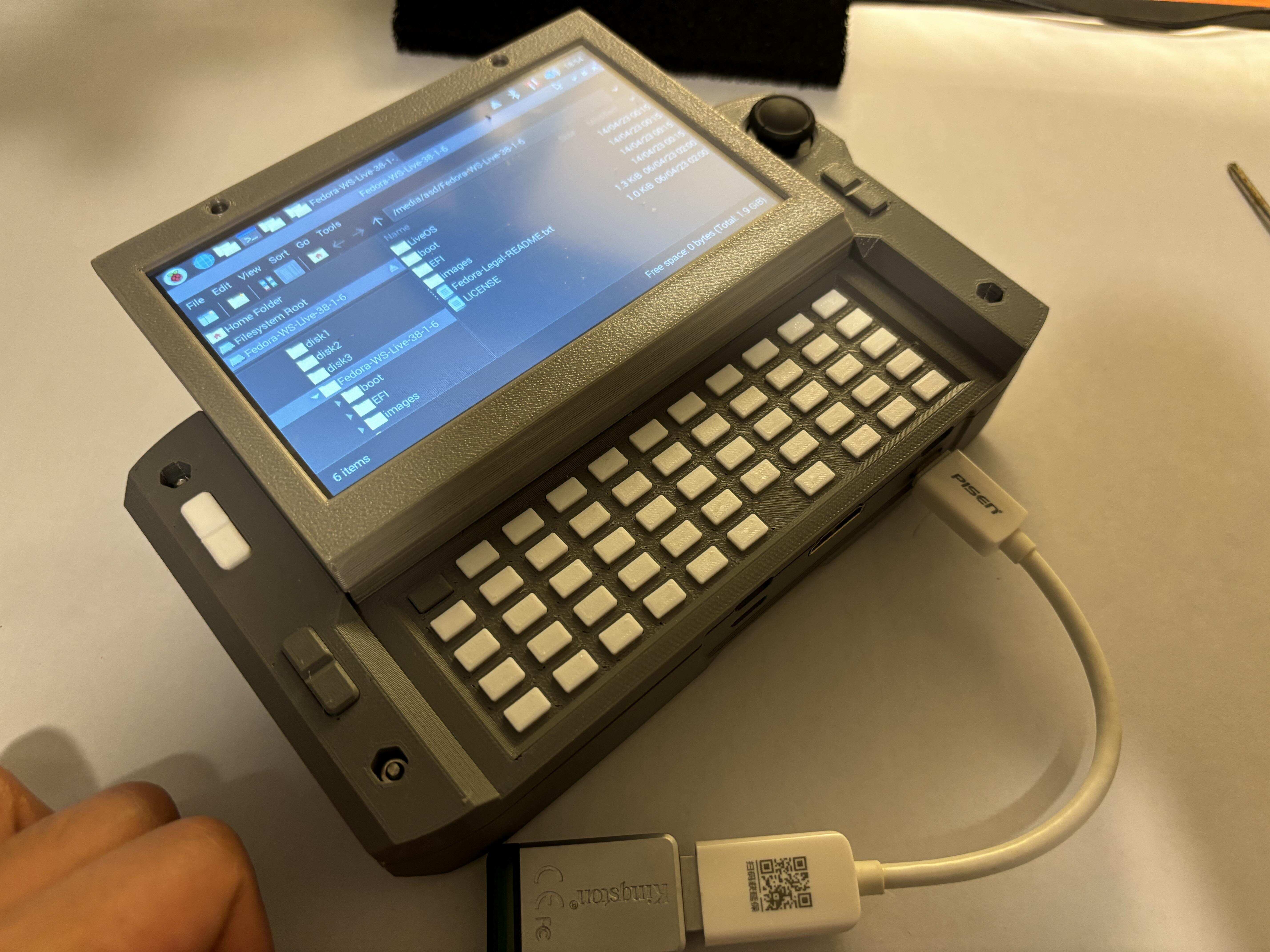
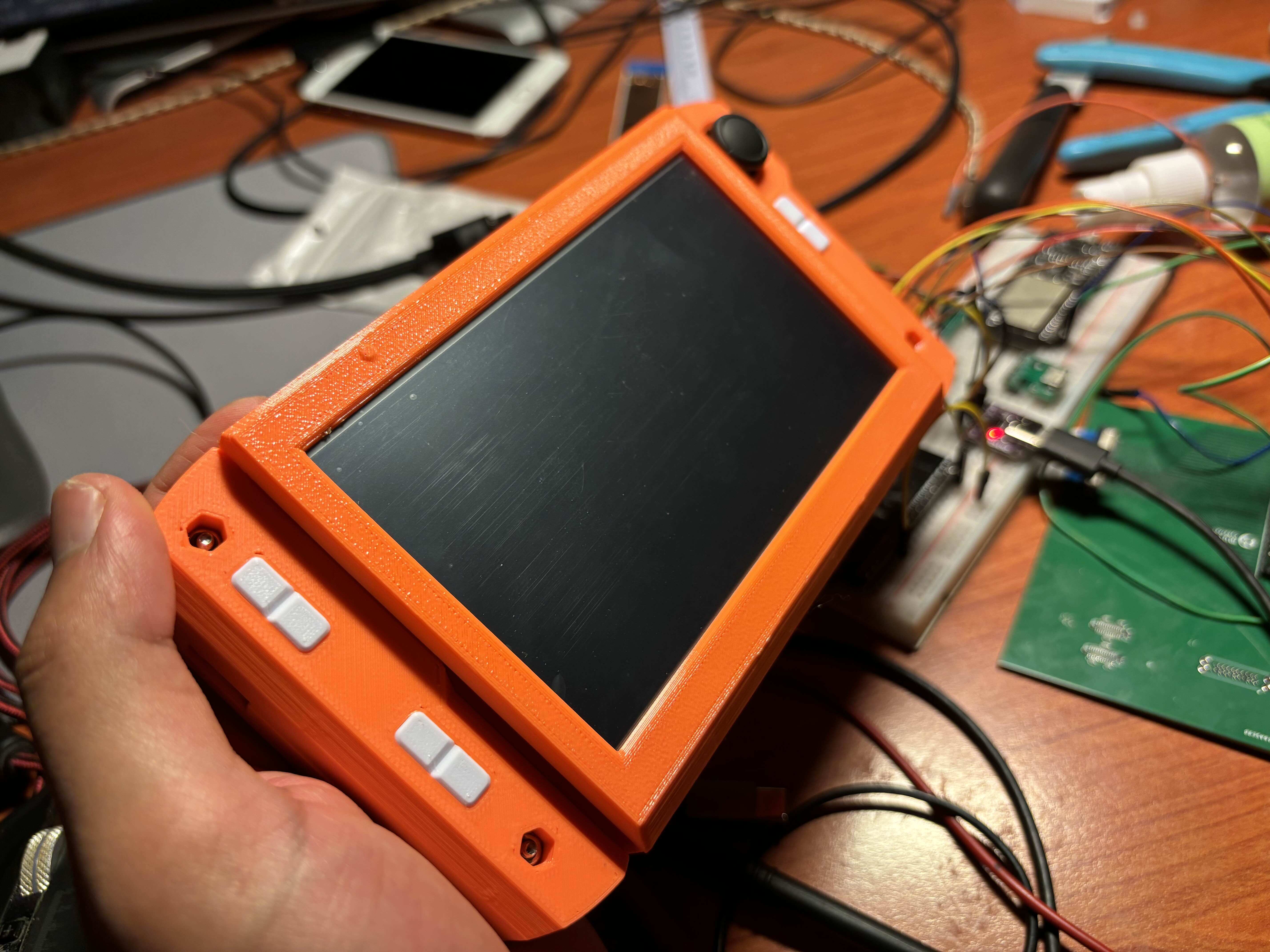
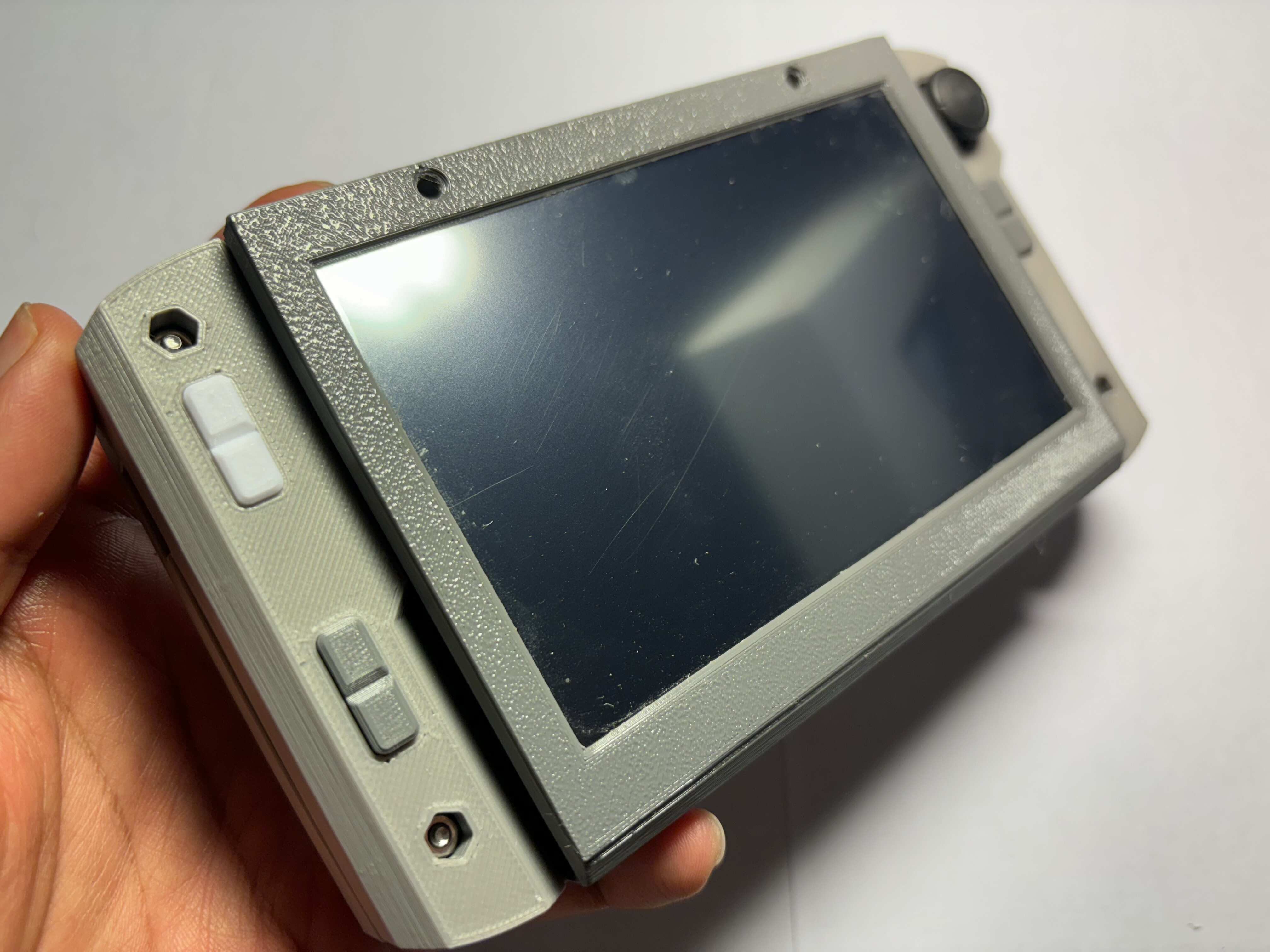
Pictures